B95Plus – Legacy
Manufacturing for this product has been discontinued. As an alternative, please refer to the B30, P747 and P74x relays.
The Multilin™ B95Plus Bus Protection System is the ideal solution for one of the biggest challenges for large bus protection: the time and cost involved in the design, installation and commissioning of the field wiring between measurements from the switchyardand the bus protection relay in the room. The HardFiber Brick, the environmentally hardened distributed bay unit of the B95Plus bus protection relay, directly reduces the time and costs involved in field wiring in both the short term and the long term.
Save time and money in the short term with flexible mounting options for the HardFiber Brick bay unit. The compact size and rugged design allows for installation in the switchyard, in equipment cabinets or in the control room. Data signals are converted to digital signals per the IEC 61850 standard and communicated over a single fiber optic cable. Installation next to the primary signal source virtually eliminates all field wiring.
To save money in the long term, use the HardFiber Brick bay unit as an IEC 61850 process bus merging unit. This becomes the complete I/O interface for protective relays and all zones of protection. Relay installation for any future zone of protection becomes plug-and-play: mount the relay on a panel, plug the relay into the HardFiber Brick bay unit and commission.
Key Benefits
- Reduce field wiring costs by replacing multiple copper wires and terminations with a fiber optic cable
- Save installation costs by mounting the bay unit in harsh environments without requiring specialized enclosures
- Increase savings by connecting other relays to the same process bus bay unit
- Protect six three-phase differential zones with one central device
Field Wiring
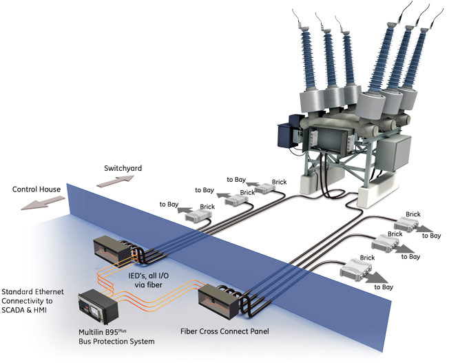
We Solve the Field Wiring Challenge with the B95Plus Bus Protection System
The Multilin B95Plus Bus Protection System changes the focus of bus protection to that of application by replacing most of the field wiring with distributed I/O and fiber optic cables. The bus protection system consists of a distributed process interface (data acquisition and tripping) architecture using HardFiber Bricks as bay units, with centralized processing performed by the B95Plus protection relay. All copper field wiring is between primary equipment in the switchyard and Bricks, which ideally should be located at the primary equipment in the switchyard. Fiber optic cables connect Bricks to the B95Plus. For all applications, the installation is then identical: the physical interface consists of Bricks connected to a fiber optic cable. A single B95Plus is mounted in a relay cabinet, with the process cards in the unit patched to the fiber optic cables coming from the Bricks.
HardFiber Brick System
The HardFiber Brick System can easily be incrementally scaled to include new equipment as stations evolve. Duplicated Bricks in the switchyard provide a drastic improvement in reliability and security over today’s technology.
Hardware
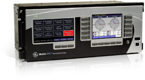
Multilin B95Plus Bus Protection Relay
The B95Plus bus protection relay unit is the heart of the system. This unit performs all processing functionality, including protection functions, metering, monitoring, FlexLogic and SCADA communications.
- Simplifies use through a Graphical User Interface (GUI) that includes configurable single line diagrams for bus sources, local control and status indication of breakers and disconnects, 20 programmable pushbuttons, and a configurable digital alarm annunciator
- Connects up to 8 Bricks for each process card while, supporting up to 12 bus sources per card
- Supports 2 process cards per unit, for a total of 16 Bricks and 24 bus sources
- Provides identical connections and installation for all bus configurations
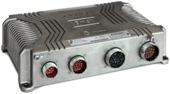
HardFiber Brick as Bay Unit
- Measurement and control for primary apparatus, including AC measurements (4 currents and 4 voltages, or 8 currents) and contact I/O (18 digital inputs and 7 digital outputs including a latching relay)
- Simple device with no field configuration or configuration settings
- Environmentally hardened for outdoor mounting in switchyards
- Connectorized cables for simple, tools-free field installation and removal
- IEC 61850 message formats for communications, including sampled value messaging for currents and voltages
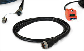
Cables
The HardFiber Brick uses connectorized cables to interface with primary equipment and with system measurements, and to interface to the B95Plus itself. The cables at the Brick end uses an IP67 certified industry standard connector designed for rugged environments. These connectors screw onto the Brick for a simple, tools-free connection. Three of the cables are copper cables used to acquire AC measurements, acquire equipment status, and provide equipment control. The fourth cable provides the fiber interface to the B95Plus central unit as well as DC power to the Brick. These cables therefore can become standard parts, manufactured in advance of installation by any cable manufacturer. These cables are also directly available from GE.
Protection
The B95Plus bus protection relay system provides robust and reliable protection for all bus protection applications. Highlights of the protection functions related to bus protection include:
- Multi-zone differential protection with both restrained (dual-slope percent or biased) and unrestrained (unbiased or instantaneous) functions incorporated.
- Differential protection is fast (typical response time: 1 power system cycle) and secure. Security is achieved by using a fast and reliable CT saturation detection algorithm and a phase comparison operating principle. Security is further enhanced by support for redundant process interface units (Bricks). Supports both three-phase tripping and individual phase tripping.
- Dynamic bus replica functionality and multi-zone protection (up to 6 zones) is supported allowing application of the B95Plus to multi-section reconfigurable buses. A zone expansion/contraction to an open breaker feature is included. Isolator position monitoring for up to 48 isolators.
- Check-zone functionality configured by programming one of the differential zones to enclose the entire bus.
- Additional bus protection functions including end fault protection, breaker fail and overcurrent protection for each bus source, CT trouble monitoring for each bus zone.
Multilin B95Plus Functional Block Diagram
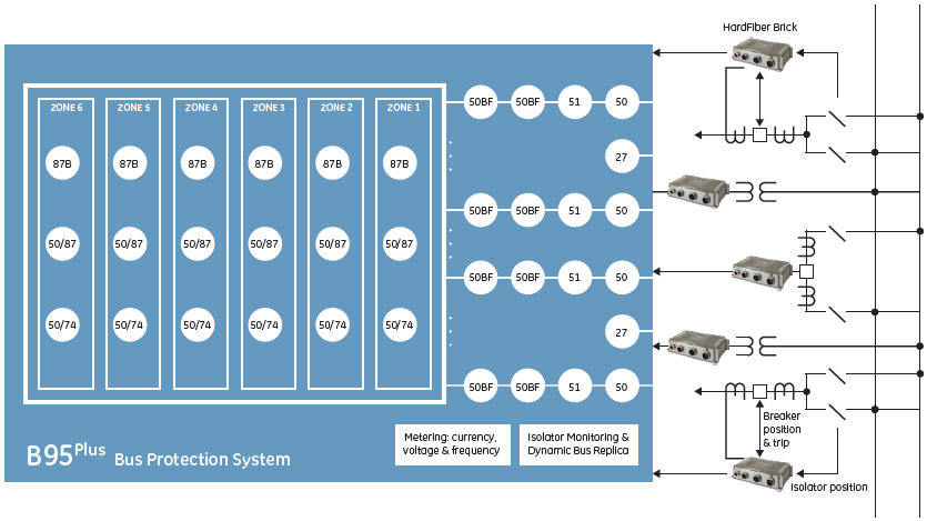
ANSI Divice Numbers & Functions
| Device Number | Function |
|---|---|
| 87B | Percent bus differential |
| 27 | Undervoltage |
| 50 | Instantaneous overcurrent |
| 50/74 | CT Trouble |
| Device Number | Function |
|---|---|
| 50/87 | Unrestrained Bus Differential |
| 51EF | End fault protection |
| 51 | Time overcurrent |
| 50BF | Breaker failure |
Applications
- Reconfigurable multi-section bus bar with up to 24 feeders
- Retrofit and greenfield installations for power generation, transmission and distribution systems
- Reconfigurable bus bars for single bus, breaker-and-a-half and double bus with and without bus couplers
- Air-insulated and GIS stations
Standardize on the B95Plus for Any Bus Configuration
The B95Plus can be applied on a multitude of bus configurations due to the distributed architecture, and includes support for up to 6 zones of bus differential protection and support for up to 24 bus sources. The physical connection and wiring architecture for the B95Plus system will be identical for any bus configuration: Bricks installed to acquire measurements and equipment status, with the B95Plus unit connected to Bricks via fiber optic cables. The relay panel design will be identical for all applications, for all bus configurations. The only difference from application to application is the number and location of Bricks, and the programming of the B95Plus unit.
Some typical bus configurations that can be protected by the B95Plus:
 Two single buses with a bus coupler
 Double bus with a bus coupler
 Breaker-and-a-half arrangement
Process Bus
Quickly Expand Protection through Process Bus
The B95Plus Bus Protection System is intended to operate as a standalone, distributed bus protection system. The bay units for this system are Bricks, part of the HardFiber IEC 61850 process bus solution. Once the Bricks for the B95Plus are installed process bus data is available for use for any other zone of protection. The Bricks, then, are a distributed I/O interface for all protection functions and zones, not just the B95Plus. With the B95Plus in place, installing line protection or feeder protection is a simple process: mount the relays in a panel, and patch to the fiber optic cable from the appropriate Bricks. The only requirement is the relays must implement the appropriate IEC 61850 datasets to interface successfully with the Bricks. All members of the Universal Relay family have the ability to interface with Bricks.
 Expand protection through process bus
Specifications
| BUS DIFFERENTIAL PROTECTION | |
|---|---|
| Number of differential zones | Six 3-phase zones |
| Max number of currents: | Total dynamic number of bus source to zone connections closed at any one moment in time up to 120 |
| CT ratio compensation range | 32:1 |
| Operating time | < 1 power system cycle - typical bus fault |
| BUS REPLICA | |
|---|---|
| Features | Dynamic bus source current assignment to each zone, dynamic zone trip assignment to each bus source, dynamic blocking of zones on CT bypassed, 1 user programmable auxiliary zone trip inputs, 3 user programmable bus source trip inputs, dynamic zone expansion/reduction |
| BUS SOURCES | |
|---|---|
| Number of bus sources | 12 per process card included in the order code |
| Current inputs | 3-phase currents |
| CT rated primary | 1 to 65000 A |
| CT rated secondary | 1 A or 5 A |
| Nominal frequency | 50 or 60 Hz |
| CT Trouble Monitoring | 1 element per bus source |
| Breaker failure protection | 1 element per bus source |
| Instantaneous Phase Overcurrent | 1 element per bus source |
| Inverse Time Phase Overcurrent | 1 element per bus source |
| VOLTAGE SOURCES | |
|---|---|
| Number of voltage sources | 2 per process card included in the order code |
| Voltage inputs | 3-phase voltages, wye or delta |
| VT ratio | 1.00 V to 24000.00 /td> |
| VT rated secondary | 25.0 V to 240.0 V |
| Nominal frequency | 50 or 60 Hz |
| ISOLATORS | |
|---|---|
| Number of isolators | 48 per process card included in the order code |
| Isolator status inputs | Form “a” and form “b” contact inputs, each optionally dual redundant |
| Configurable failsafe modes | 2Open, closed, last valid state |
| Monitoring | Alarm on inconsistent inputs persisting longer than a user set time |
| TRANSIENT RECORDER | |
|---|---|
| Storage capacity | Five records with all channels recorded, at 128 samples per cycle, spanning 1 second with no retriggers |
| Number of records | 1, 2, 5, 10, 20, 30, 40, or 50 records |
| Sampling rate | 16, 32, 64 or 128 samples per power cycle |
| AC waveform channels | All enabled bus sources and voltages sources |
| Analog channels | Magnitudes and angles of all ac waveforms recorded plus all enabled zone differential and zone restraint phase current magnitudes and angles |
| Digital channels | 128 user configurable channels on the main card and 128 user configurable channels on each process card |
| Configurable digital data | Any FlexLogic™ operand |
| Storage modes | Automatic overwrite, protected |
| Triggering modes | Time window from rising edge of trigger, continuous recording up to 4 additional basic record lengths as long as retrigger is active |
| Pre-trigger window | 0 to 100% of the basic record length |
| Data storage | non-volatile memory |
| EVENT RECORDER | |
|---|---|
| Storage capacity | 8,192 events plus 8,192 events on each process card |
| Time tag: | to 1 µs |
| Triggers | all FlexLogic™ operand activations |
| PROCESS I/O | |
|---|---|
| Number of process bus ports | 8 per process card |
| Port type | 100Base-BX-D, in SFP package with LC 50/125µm multi-mode connector |
| Transceiver diagnostics | per SFF-8472 |
| Brick synch frame jitter | ±1µs |
| POWER SUPPLY | |
|---|---|
| Nominal DC voltage | 125 to 250 V |
| Minimum DC voltage | 80 V |
| 1Maximum DC voltage | 300 V |
| Nominal AC voltage | 100 to 240 V at 50/60 Hz |
| Minimum AC voltage | 80 V at 48 to 62 Hz |
| Maximum AC voltage | 275 V at 48 to 62 Hz |
| Voltage withstand | 2 × highest nominal voltage for 10 ms |
| Voltage loss ride-through | 200 ms duration at nominal input voltage |
| Power consumption | 150 VA maximum |
| PROCESS CARD OPTICAL | |
|---|---|
| Number of transceivers | 8 |
| Transceiver type: | Transmit 1550 nm, receive 1310 nm, 100Mb/s, bi-directional single-fiber 50/125µm multi-mode module (levels comply with IEEE 802.3 standard 100Base-BX-D) |
| Optical transmit power | –14 to –8 dBm |
| Maximum optical input power | –8dBm |
| Optical receiver sensitivity | –30dBm |
| Termination | LC fiber connector |
| Laser class | Class 1. This product is eye-safe under all operating conditions. |
| REMOTE RESOURCE SPECIFICATIONS | |
|---|---|
| Number of field units | 8 per process card |
| Number of field contact inputs | 1 for each brick contact input |
| Number of field contact outputs | 1 for each brick contact output |
| Number of field latching outputs | 1 for each brick latching output |
| Number of shared inputs | 16 per process card |
| Number of shared outputs | 16 per process card |
| APPROVALS AND CERTIFICATION | |
|---|---|
| Compliance | CE, UL, ISO |
| Compliance | Applicable Council | Directive According To |
|---|---|---|
| CE | Low voltage directive | EN 60255-27 (normative sections) |
| EMC directive | EN 60255-26 / EN 50263 EN 61000-6-5 (Area G) | |
| UL | cULus | UL 508 UL 1053 C22.2 No 14 |
| ISO | Quality management system | ISO 9001 |
Recommended Products & services

Bus Protection
GE provides enhanced reliability through advanced protection for a wide range of bus...
View More