Static Var Compensator Solutions
Increasing Grid Reliability
GE Vernova’s Static Var Compensator (SVC) solutions are a cost-effective and efficient means to provide dynamic voltage support and maintain the reliability and efficiency of power supply. These solutions are highly reliable, easy to integrate into both existing and new infrastructures, and reduce the investment required for building new network extensions.
GE Vernova Advantage
GE Vernova’s SVC solutions are customized based on the utility’s technical and economic requirements for their network such as fault level and load parameters. GE Vernova provides an extensive services portfolio comprised of feasibility and network studies, project management, engineering capabilities, equipment, installation services and long term maintenance contracts, delivering an integrated and robust system that provides utilities with the following competitive advantages.
Model Based Design Control ensures optimal and accurate performance of the SVC by direct deployment into the system software
- Rapid technical responsiveness to the customer, from planning support and project execution to commissioning
- Intuitive graphical interface provides fast, automatic, and error free code generation from control models, ensuring a greater level of confidence to the customer
- Ease of integration into control system software with power system modeling tools such as PSCAD provides an accurate representation of system performance for planning and transients analysis
- Modular hardware design based on commercial off-the-shelf components which provide extensive scalability to any project rating, while maintaining quick system delivery time and simple life-cycle Management
Classic SVC and GE Vernova’s patented Main Reactor SVC provides more design flexibility to ensure optimized system performance
- Broad range of SVC configurations including: classic, hybrid, Main Reactor, fixed, modular, relocatable, low noise, and reduced footprint designs
- Ground level power to the thyristor valves provide system voltage independence and benefits operation at very low voltages, increasing SVC readiness during severe system events
- Unique Main Reactor configuration improves harmonic performance, reduces operational losses and design footprint, and ensures regulatory compliance at the point of interconnection
Manufacturing excellence and deep domain technical expertise providing full system lifecycle support resulting in simplified and streamlined commercial offerings
- Deep technical expertise gained though more than 50 years’ experience on more than 380 global installations ranging from small industrial to large utility projects, in diverse applications and extreme environmental conditions
- Full range of lifecycle support competencies including network analysis, system design, engineering, procurement, civil works, installation, testing and commissioning and asset management, eliminating project and logistical complexities of multiple vendor projects
- SVC main components are vertically integrated within GE Vernova’s advanced manufacturing facilities, which are certified to ISO 9001, ISO 14001 Environmental Standards and OHSAS 18001
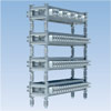
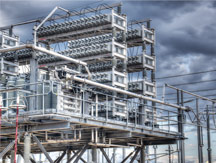
GE Vernova’s Classic SVC Design
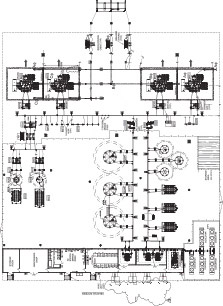 -100/+200Mvar classic SVC design
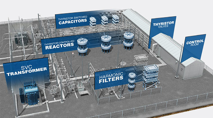
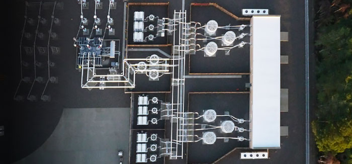
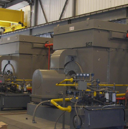
GE Vernova’s Classic SVC design is customized based on the utilities key requirements for system performance. Every system is tested extensively during factory acceptance testing and site commissioning to ensure guaranteed performance.
Benefits of classic SVC design:
- Allows grid operators to gain accurate control of network reactive power and voltage
- Increases power transfer capability
- Improves steady-state and dynamic stability of the grid with very fast response times
Main components of the system include:
- SVC transformers
- Thyristor Controlled Reactors (TCR)
- Thyristor Switched Capacitors (TSC)
- Harmonic Filters
- Advanced Thyristor Valve (ATV)
- Advanced Digital Control (ADC)
- Protection and Auxiliary systems
- Thyristor valve cooling system
System ratings include:
- Typical utility voltage levels: approx. 69 < kV < 800
- Typical utility overall ratings: approx. 40 < Mvar <1,200
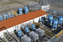
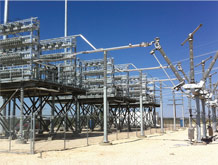
Example of a classic SVC design
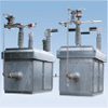
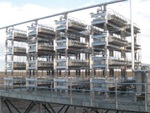
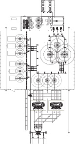 -100/+200Mvar Main Reactor design, with smaller footprint
GE Vernova’s Patented Main Reactor SVC Design
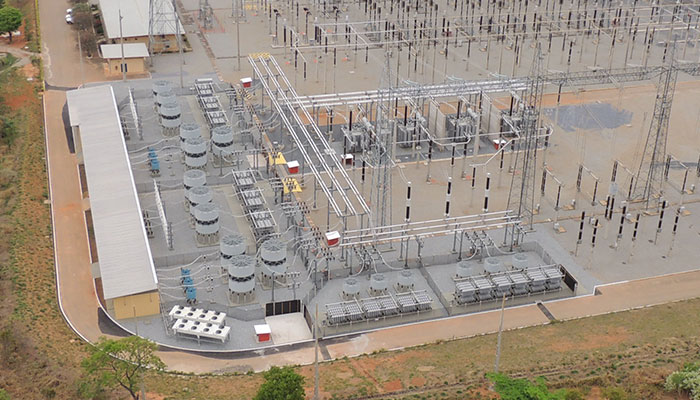
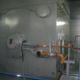
GE Vernova’s patented Main Reactor SVC design is customized based on the utility’s key requirements for system performance. Every system is tested extensively during factory acceptance testing and site commissioning to ensure guaranteed performance.
Traditionally, the SVC medium voltage bus is connected directly to the SVC coupling transformer, but with the main reactor configuration there is a reactor connected between SVC bus and coupling transformer.
The Main Reactor concept efficiently isolates harmonics, even in demanding network conditions. This design requires fewer harmonic filters enabling a compact, optimized SVC layout.
The Main Reactor has many other inherent benefits for improved harmonics, simpler design and cost savings, including:
- Main Reactor blocks harmonics generated by the SVC
- Lower amount of filtering is needed
- Improved harmonic distortion at the Point of Common Coupling
- Less harmonic stress on the SVC coupling transformer
- Lower voltage stress on all components
- Minimized requirement for Thyristor Switched Capacitors (TSC), potentially eliminated
- Thyristor Controlled Reactors (TCR) has smaller coils, lower losses and reduced number of thyristor valve levels
- Only low order filters are needed (reactor blocks high order), wide filtering band can be used
Main components of the system include:
- SVC Transformers
- Thyristor Controlled Reactors (TCR)
- Main Reactor
- Harmonic filters
- Advanced Thyristor Valve (ATV)
- Advanced Digital Control (ADC)
- Protection and Auxiliary systems
- Thyristor valve cooling system
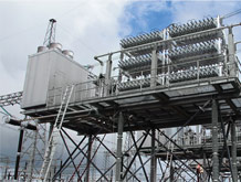
Example of a Main Reactor SVC design
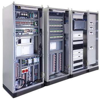 Advanced Digital Control platform for SVC systems
GE Vernova’s Advanced Digital Control for SVC Systems
GE Vernova’s approach to SVC Control System represents the latest in design methodology by utilizing a powerful Model Based Design approach. With this approach the SVC Control System software is built using a core library of complex control algorithms that represents over 50 years of FACTS experience within GE Vernova. Model Based Design utilizes a graphical interface for the design stage and translation of control models with automatic code generation for all testing and verification stages. With this approach, GE Vernova has enhanced the quality, reliability, and maintainability of the Advanced Digital Control system for SVCs.
Model Based Design Advantages
- With Model Based Design, programming and customization of control functions is simplified by the use of a graphical programming interface.
- Testing and verification of the control system at the design stage starts early using real-time control models in closed loop with the SVC power electronics and the power grid.
- Simulation environment uses real-time control models providing the most accurate representation of control performance. The control models can be easily exported to PSCAD™ or similar tools with one-to-one representation for further testing and simulations.
- Automatic code generation allows direct conversion of graphical control models into real-time control software, eliminating the manual “coding stage”, resulting in improved quality and reliability.
- Complete traceability of customer requirements throughout the control model provides easy and efficient way for software modifications and new feature implementation at any stage of the project.
- Model Based Design approach adopted by GE Vernova has already revolutionized the development approach for critical control software in aviation, space and automotive industries, resulting in significant improvement in software quality for critical and life-supporting applications.
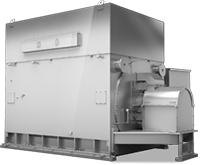
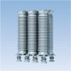
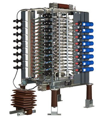 GE Vernova's Advanced Thyristor Valve
Thyristor Controlled Reactor and Thyristor Switched Capacitors
Thyristor valves are used for controlling reactive power in Static Var Compensators. Thyristor Controlled Reactor (TCR) valves are used to control the effective fundamental frequency current in the reactors by controlling the conducting ratio through varying the firing angle of the thyristors. Thyristor Switched Capacitors (TSC) bank valves are used for switching capacitor banks on or off according to the reactive power demand on a time scale of several periods or more.
Advanced Thyristor Valve for SVC Systems
The Advanced Thyristor Valve (ATV) is GE Vernova’s latest range of liquid-cooled thyristor valves for Static Var Compensator applications. These thyristor valves have been developed by drawing on GE Vernova’s extensive experience of more than 50 years of applying thyristor based SVCs both for transmission and industrial applications. The ATV provides a very compact, versatile and standardized platform for both TCR and TSC variants.
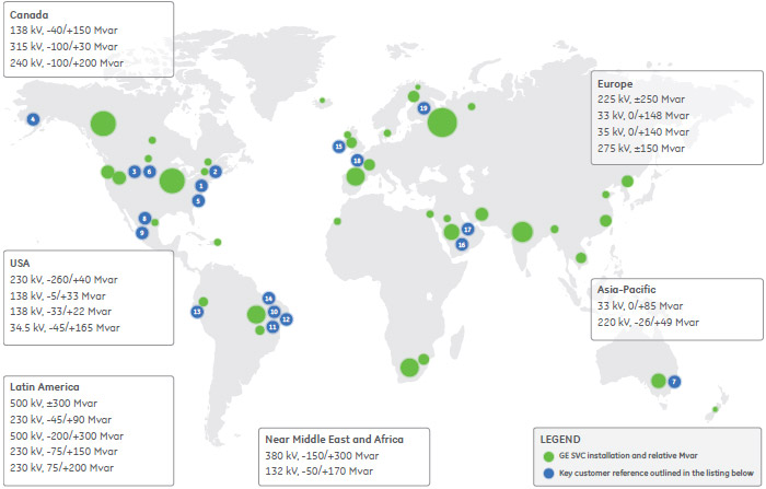
GE Vernova Experience
GE Vernova has designed, delivered and supports over 380 Static Var Compensator Systems globally in a broad range of applications and environments. The below details are a selected representation of recent projects, a complete reference list is available upon request.
Customer References
- Location: West Wharton, NJ, USA
Rating: -260/+40 Mvar, 230 kV - Location: St-Marc-de-Figuery, Canada
Rating: -100/+300 Mvar, 315 kV - Location: Alberta, Canada
Rating: -100/+200 Mvar, 240 kV - Location: Alaska, USA
Rating: Refurbishment of 3 SVCs - (-22 to +22 Mvar) - Wasilla,
AK-(-5 to +33 Mvar) - Fairbanks, AK-(-33 to +22 Mvar) - Healy, AK - Location: Roanoke, VA, USA
Rating: -45/+165 Mvar, 34.5kV (138 kV) - Location: Pasqua, Saskatchewan, Canada
Rating: -40/+150 Mvar in 2x(-20/+75) Mvar, 138 kV - Location: State of Victoria, Australia
Rating: -26/+49 Mvar, 220 kV - Location: Veracruz, Mexico
Rating: -60/+180 to 0/+240 Mvar, 34.5 kV - Location: Mexicali, Mexico
Rating: -75/+200 Mvar, 230 kV - Location: Brazil
Rating: -200 / +300 Mvar, 500 kV - Location: Brazil
Rating: -75 / +150 Mvar, 230 kV - Location: Brazil
Rating: -75 / +150 Mvar, 230 kV - Location: Peru
Rating: ±15 Mvar, 138 kV - Location: Imbirussu, Brazil
Rating: ±100 Mvar, 230 kV - Location: Scotland, UK
1st Installation of GE Vernova’s patented Main Reactor design
Rating: -150 / +150 Mvar, 275 kV - Location: Quway’iyah, Saudi Arabia
Rating: +170 /-50 Mvar SVC - Location: Saudi Arabia
Rating: +300/-150 Mvar SVC and expansion of 110kV GIS at 380kV BSP and two 110kV, 100Mvar bus connected shunt capacitors at 380kV BSP - Location: La Merlatiere and Domloup, France
Patented Main Reactor Design
Rating: ±250 Mvar at 225 kV - Location: Kangasala, Finland
Rating: -200/+240 Mvar, 400 kV - Location: Albany, New Zealand
Rating: ±100 Mvar, 220 kV
Recommended Products & services
Static Var Compensator Solutions
GE Vernova’s Static Var Compensator (SVC) solutions are a cost-effective and...
View MoreSynchronous Condenser
Cost Effective Power Transfer
GE Vernova’s Synchronous Condenser Systems are engineered and designed to provide a highly reliable and efficient solution to address reactive compensation and voltage support requirements, providing transmission operators an optimized solution for cost, performance and operational flexibility.
Synchronous Condenser
Cost Effective Power Transfer
GE Vernova’s Synchronous Condenser Systems are engineered and designed to provide a highly reliable and efficient solution to address reactive compensation and voltage support requirements, providing transmission operators an optimized solution for cost, performance and operational flexibility.
Today’s Challenging Environment
For most utilities ensuring grid reliability, efficiency, and security is a primary concern. As the grid evolves and load profiles change, stresses are being put onto transmission and distribution networks, making the work of grid management much more challenging. Globally, utilities are facing many grid challenges and market condition changes including:
- Changes in generation mix
- Decrease in conventional generation
- Increase in renewable and distributed generation
- Environmental and regulatory policy changes, driving the retirement of traditional coal generating stations
These challenges have an operational impact on the electrical infrastructure, in particular creating an overall deficiency in:
- Reactive compensation support
- Voltage support
- System inertia
- Low short circuit ratios on the network
GE Vernova’s Solution
GE Vernova offers transmission utilities a simple and reliable solution to address reactive compensation and voltage support requirements. Our newly re-designed motor based Synchronous Condensers are custom designed to provide transmission operators with a proven, robust and reliable solution.
| GE Vernova Synchronous Condenser Overview | |
|---|---|
| Ratings | Range from 10 to 300 Mvar+ per machine |
| Rotor | Round 2-Pole or Solid Salient Pole |
| Poles | 2, 4 or 6 |
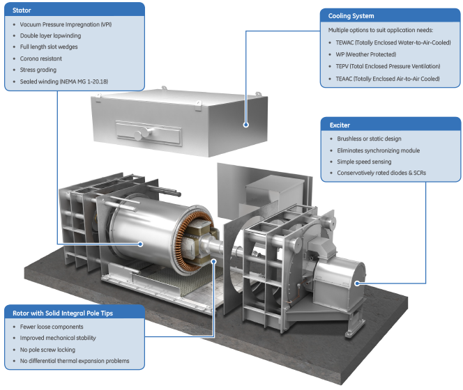
| Excitation | Static or Brushless |
| Starting | Full Voltage, Reduced Voltage, Reactor start, Pony Motor |
| Cooling | TEWAC, TEAAC, WP, TEPV |
The GE Vernova Advantage
GE Vernova’s Synchronous Condenser Systems are engineered and designed to provide a highly reliable and efficient solution, providing an optimized solution for cost, performance and operational flexibility.
Modular design resulting in operational flexibility and decreased down time
GE Vernova has combined multiple synchronous condenser machines into systems that allow for reduced overall footprint, customize Mvar ratings and maintenance flexibility for utilities to reduce operational downtime.
Robust design with extended life resulting in minimal maintenance
GE Vernova synchronous condensers have superior construction, resulting in high efficiency, reliability, and provide easy access for routine maintenance and low vibration for a long life.
Customized design and use of innovate technology resulting in increased reliability and reduced risk of failure
Unique forged integral pole tip design well suited to high load inertia applications. Low mechanical stress is achieved through:
- Fewer loose components
- Improved mechanical stability
- Reduced hot spots during starting
- No pole screw locking concerns
- No differential thermal expansion problems
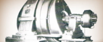
- Proven experience including the world’s largest 1,800rpm motor
Extensive experience resulting in seamless integration into the utility transmission grid
GE Vernova leads the industry with more than 100 years of experience and the proven synchronous condenser design has been applied in over 200 applications.
Key Benefits of GE Vernova’s Synchronous Condensers

Short-term Overload Capability
The GE Vernova Synchronous Condenser has a large current overload capability. which can provide beneficial system support during emergencies or short term contingencies. As can be seen below, a GE Vernova Synchronous Condenser can provide more than two times its rating for up to 10 seconds. The machine’s significant overload capability can be accounted for in choosing the size of the machine required.

Low Voltage Ride Through
The GE Vernova Synchronous Condenser system has the ability to remain connected and to provide the necessary system benefits even under extreme low voltage contingencies. Mechanical inertia combined with state of the art excitation provides smooth reliable support that is naturally compatible with generation. Power electronic-based solutions do not have mechanical inertia and therefore cannot deliver comparable ride-through performance.

Provides System Inertia
Inertia is an inherent feature of a Synchronous Condenser, since it is a rotating machine. The benefit of this inertia is improved frequency regulation where more renewable generation is being added or where existing generation is being retired.

Response Time
GE Vernova Synchronous Condensers are fast enough to meet dynamic response requirements by using modern excitation and control systems. GE Vernova has integrated today’s advancements in control technologies into a proven machine design to make that solution better than ever.

Short Circuit Contribution
Synchronous Condensers provide real short circuit strength to the grid. Increased short circuit improves system stability with weak interconnections, facilitates system protection and can improve the operation of modern power electronics installations.

Minimal Harmonic Generation
The Synchronous Condenser is not a source of harmonics and can even absorb harmonic currents. The lack of harmonics help make the synchronous condenser friendly to the surrounding grid and other devices. This provides for ease of integration into existing networks.

Minimal Network Interactions
The GE Vernova Synchronous Condenser mitigates system control interaction concern by utilizing traditional and robust electrical components combined with state of the art control architecture that does not cause undesirable interactions with your existing FACTS devices.
Installation & Maintenance Benefits

Fast Project Cycle Time
The system only requires integration to commonly available power delivery components resulting in accelerated project cycle times. The design, manufacture, installation and commissioning of a Synchronous Condenser system can be completed within 16 months. GE Vernova’s experienced Power Projects team has 99% record of on-time project completion and greater than 98% on-budget execution.

Proven Design and Increased Reliability
The GE Vernova Synchronous Condenser is designed to provide trouble-free, reliable service and is a proven solution with more than 200 applications over nearly a century. Advancements in materials and manufacturing techniques, combined with modern control technologies, have greatly improved the reliability and functionality of this robust, time-tested solution. Operators can now utilize the simplicity of electro-mechanical system combined with the benefits of a state of the art excitation and control system in order to meet their grid support needs.

Minimal Maintenance
The GE Vernova Synchronous Condensers proven design requires minimum maintenance resulting in minimal operating costs and reduced total cost of ownership.
Core Components
GE Vernova’s Synchronous Condenser system consists of components commonly used in electric utilities and industrial facilities, with proven robustness and reliability.
Integrated Intelligent Controls

Control Systems & Protection Relays
- Proven controls architecture
- Multilin multi-function digital protection relays
- Secure communications infrastructure
- Human Machine Interface (HMI) operator friendly
- Digital solid state controls

Power Delivery Equipment
- Generator Step Up (GSU) transformer
- HV/MV circuit breakers & switches
- Ancillary systems (lube oil skid)
- Starting reactors
- Instrument transformers (CT/VT)
Typical Applications

HVDC
- Provides Short Circuit Strength
- Dynamic reactive power support (voltage regulation)
- Reduces local harmonic distortion (filter)

Wind/Solar
- Improves or increases short circuit ratio (SCR)
- Dynamic voltage support
- Can improve and extend wind plant capacity ratings
- Provides inertia to improve frequency regulation
Synch Condenser Upgrades
- Higher reliability and efficiency
- Lower total cost of ownership
- Modern controls and excitation – improved response time

Grid Code Compliance
- Enhanced ROCOF (Rate of Change of Frequency)
- Improved LVRT (Low Voltage Ride Through)
Grid Support
- Local voltage support during contingencies and faults
- Provides short term overload capability
- Improves weak AC grid performance
- EHV cables
- Excessive shunt compensation
- Weak AC Grid

Regulatory/Environmental
- Condenser can replace the dynamic voltage regulation and inertia from retired units
- Allows utility to maintain system performance and grid stability
- EPA Coal Requirements
- Once thru cooling requirements
- Generation Retirements
Customer Case Studies
Customer Name
Vermont Electric Company (VELCO)
Location
Granite Substation, Vermont, USA
Application / Challenge:
As part of the Northwest Vermont Reliability Project a number of upgrades were investigated to provide for the reactive power needs at the Granite substation. Simulations indicated that the power system is very near a point of voltage instability. In the case of an outage of the Vermont Yankee – Coolidge 345kV line, a continuous reactive power control device is critical to prevent voltage collapse.
Solution:
- Qty (4) +25/-12.5 Mvar sync condensers
- Qty (4) 25 Mvar shunt banks (MSC)
- Qty (2) Phase shifting transformers
- Integrated control system
Reasons cited for the synchronous condenser over static devices include low voltage ride through capability and the high short time overload characteristics. The overload capability of the condensers provides sufficient time for the mechanically switched 115kV shunt capacitors to be placed into service.
Customer Name
Korea Electric Power Company (KEPCO)
Location
Jeju Converter Station Jeju Island, Korea
Application / Challenge:
The function of a synchronous condenser system in a weak AC grid, and especially one that connects via an HVDC converter terminal, is to improve short circuit strength, provide inertia, and improve reliability.
Solution:
GE Vernova supplied two +50/-25 Mvar synchronous condensers to KEPCO that allow the Chejuu-Haenam HVDC link to continue to cost effectively and efficiently provide power to the island.
With successful installation of the synchronous condensers, KEPCO will be able to retire their existing, converted gas turbine synchronous condensers and transport more power on the existing grid network.
Recommended Products & services
Synchronous Condenser
GE Vernova’s Synchronous Condenser Systems are engineered and designed to provide a...
View MoreSeries Compensation Systems
Cost Effective Power Transfer
GE Vernova’s Series Compensation System allows utilities to cost effectively increase power transfer capabilities of their existing infrastructure and new transmission lines.
Series compensation systems are installed in series with the High Voltage transmission line, and consist of an integrated, custom-designed system with many power capacitors arranged in series and parallel. The most critical equipment is the parallel protective system that prevents damage to the capacitors during power system faults.
Series Compensation Systems
Cost Effective Power Transfer
GE Vernova’s Series Compensation System allows utilities to cost effectively increase power transfer capabilities of their existing infrastructure and new transmission lines.
Series compensation systems are installed in series with the High Voltage transmission line, and consist of an integrated, custom-designed system with many power capacitors arranged in series and parallel. The most critical equipment is the parallel protective system that prevents damage to the capacitors during power system faults.
Overview
Today’s transmission system is becoming increasingly complex and is expected to carry bulk power in ways it was never designed for. The expectation is that transmission requirements will only increase, as power generation sources continue to evolve. GE Vernova’s Series Compensation System allows utilities to cost effectively increase the power transfer capabilities of their existing infrastructure and new transmission lines, leveraging GE Vernova’s capabilities as outlined below.
Extensive Global and Unmatched Technical Experience
A worldwide leader in executing and delivering series compensation projects, in a broad range of utility environments resulting in reduced implementation risk.
- More than a century of experience designing transmission networks, including the first series compensation project in 1928
- Leading the industry by delivering over 30,000 Mvars of series compensation systems in the last three years
- Globally recognized as the foremost technical experts for power system projects since 1928
Industry Leading Patented Technology
Providing superior systems enabled by GE Vernova’s innovate products resulting in project cost savings and increased quality and reliability.
- Fastest Triggered Air Gap (TAG) available in the industry
- Newly patented TAG and Platform Damping Technologies
- Pioneered the use of SSR filter technology in a series capacitor system
Best-in-class Quality and Process Standards
Industry leading and well-established set of project management processes and procedures, certified to ISO® 9001 standards, resulting in on-time and on-budget execution.
- 99% record of on-time project completion
- Greater than 98% on-budget execution
- Over 3.6 million hours of project execution without an OSHA® recordable incident
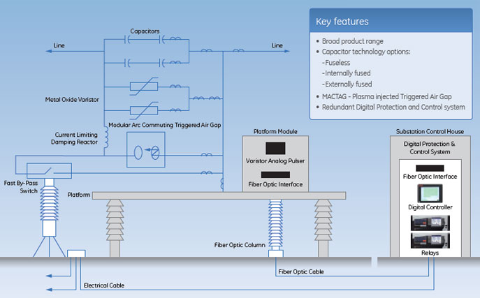
Components of a Series Capacitor Bank
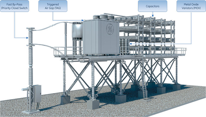
Series Compensation System Components
GE Vernova’s Series Compensation System is comprised with industry leading and patented technology, helping customers achieve high reliability and lowest possible losses on their transmission lines. The major components of the Series Compensation System include Capacitors, Metal Oxide Varistors, Triggered Air Gap, and Fast By-Pass Switches.
Capacitors
The capacitors are placed in series on a transmission circuit intended to reduce the overall line impedance and offers improved load division on parallel circuits, system transient and steady state system stability and allows for increased power transfer capability.
Modular Arc Commutating Triggered Air Gap (MACTAG)
A MACTAG is often used as an intermediate bypass device and is faster than the bypass switch, but not instantaneous like the Metal Oxide Varistor (MOV). GE Vernova’s patented design uses plasma injection to establish an arc which bypasses the capacitors and MOV until the bypass switch can close. GE Vernova’s MACTAG is the fastest in the industry (< 0.3 ms) as it does not rely on ground-based controls to initiate a bypass. A MACTAG lowers MOV cost by reducing the required MOV energy absorption.
Metal Oxide Varistor (MOV)
MOV are the primary device that protects the capacitors from overvoltage by diverting fault current. The MOV are semiconductors that conduct above a specific voltage, known as the Protective Level Voltage. The MOV limits the voltage across the capacitor bank to a safe value for the capacitors handling very high current for short periods of time and protect the capacitors until another bypass path is established.
Fast By-Pass (Priority Close) Switch
The Fast By-Pass Switch closes rapidly to limit both MOV and TAG energy, removing the series capacitors from service. This switch is also used for normal switching to insert the series capacitors or bypass them.
Series Capacitor Bank – One Line Diagram
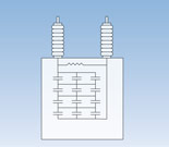
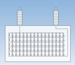
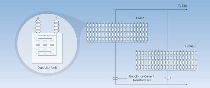
Capacitor Options
GE Vernova’s Series Compensation offerings include three capacitor options: fuseless, internally fused or externally fused. GE Vernova works with customers to evaluate their requirements and determine the best technical solution to meet customer needs to ensure, reliable and cost effective system.
Fuseless Design
- Lowest losses, typically < 0.12 watts/kvar
- High reliability: A lower internal element voltage stress rise for the same number of internal failures in comparison to an internally fused option
- A higher unbalanced current for the same internal element voltage stress
- Fault tolerance with continued operation even with failed rolls
- GE Vernova recommended option
Internally Fused Design
- Losses typically > 0.15 watts/kvar
- One fuse per internal roll. Each roll is protected by an internal fuse element
- The fuse allows a roll to fail as an open circuit
- There are multiple rolls in parallel. This places a very small incremental stress on adjacent rolls when a fuse operates. This helps prevent a cascading failure within an individual can
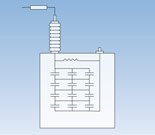
Externally Fused Design
- One fuse per capacitor unit. Fewer connections mean fewer points of failure
- Facilitates easy identification of a failed unit as the blown fuse is obvious
- Once the standard, now limited specialty applications
GE Vernova's Fuseless Design
GE Vernova recommends the fuseless option, which has been the dominant technology since the late 1990’s and is proven with a long term field failure rate of less than 0.03% per year. The film foil capacitor is a proven GE Vernova design that has been in use since the 1970s. The fuseless design produces the highest unbalance current (easy to detect a failed roll) with the lowest voltage stress on the remaining units (lower chance for a cascading failure). The diagram below depicts the two capacitor groups.
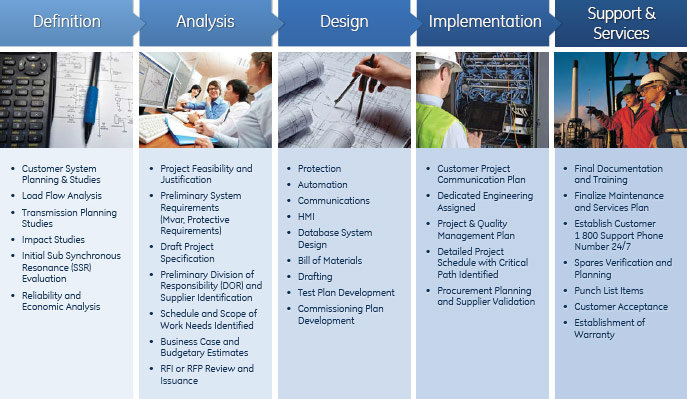
Project Management Approach
The GE Vernova project team represents unsurpassed worldwide power system engineering capabilities, comprehensive system design expertise, and unequaled project management experience. Our strength in each of these areas enables us to deliver a highly reliable solution that will fully meet your power system requirements. With each reactive compensation project GE Vernova undertakes, this team is committed to delivering 100% satisfaction.
Professional Services Process and Key Activities
Global Experience and Application Examples
GE Vernova’s Series Compensation Systems brings together an extensive portfolio of products, services and engineering excellence to deliver the next generation systems for customers based on specific requirements to address both technical and business objectives as well as support several applications. GE Vernova provides highly reliable and efficient designs that have low overall maintenance and cost of ownership. Below are just a few of GE Vernova’s selection of customer applications.
Cross Texas Transmission
Three Phase Bank Rating: 2 x 716 Mvar
Substations: Turkey, Texas – Cross Station 1 & 2
Customer Challenge
Maintain voltage stability and efficient operations of the Texas Transmission System under minimum and maximum export of wind power.
Customer Application
50% compensation on 2 transmission lines from Tule Canyon to Tesla required series compensation to reduce the inductive line impedance compiled due to long line length.
Customer Benefit
Ability to maximize amount of wind power to be transferred across the new 345 kV transmission lines.
Electricity of Vietnam
18 banks from 2012 - 2016
6,588 total Mvar in operation and awarded
Customer Challenge
Improve capacity of the 500 kV Vietnam transmission system with a compressed amount of time of less than 12 months to install systems.
Customer Application
Increase in the power transfer capability of existing transmission lines.
Customer Benefit
Increased reliability of existing transmission systems, improved voltage support and amount of power transfer capability and timely delivery of equipment meeting compact schedule requirements.
Electric Transmission Texas, LLC
Joint venture a joint venture between subsidiaries of American Electric Power and Berkshire Hathaway Energy
Edison, Gauss, Kirschoff, and Orsted Substations.
Customer Challenge
Need to provide reliable and efficient power across the new 345-kV transmission lines required to maximize the transfer of renewable generation. Must not negatively interact with the existing generation or system – Sub Synchronous Resonance concerns.
Customer Application
Eight series compensation banks located at four different sites to enable the maximum amount of power transfer capability on new 345-kV transmission lines in the CREZ regions throughout Texas.
Customer Benefit
Reliable and efficient means to transfer power from renewable generation on the new 345-kV transmission lines in the CREZ areas.
BPA (Bonneville Power Administration)
Three Phase Bank Rating: 2 X 675 Mvar
Substations: Bakeoven 1 & 2
Customer Challenge
Need to provide reliable and efficient power across the 500 kV California-Oregon Intertie . Required to increase the overall power transfer capability across the tie to facilitate the increase in capacity requirements from renewable generation projects being added to the regional system.
Customer Application
To enable the maximum amount of power transfer capability on the California-Oregon 500 kV transmission intertie.
Customer Benefit
Reliable and efficient means to transfer power from renewable generation on the new 500 kV transmission California-Oregon Intertie. GE Vernova supported a staged fault test performed by BPA, which demonstrated the capability of the GE Vernova Series Capacitor banks to withstand a close-in fault with no damage.
Modular Arc Commutating Triggered Air Gap (MACTAG)
GE Vernova’s family of Modular Arc Commutating Triggered Air Gap (MACTAG) solutions represent the industries leading technology for fast protective devices. The patented technology provides fast, reliable bypass protection, which can reduce the amount of Metal Oxide Varistors (MOV) required on a series capacitor bank resulting in project cost savings.
Customers can realize the following potential advantages with GE Vernova’s MACTAG solutions including:
- Enhanced Fault Durability and Voltage Withstand Performance
- Higher Protective Level Ratings with Fast Recovery Time Validated by Independent 3rd Party
- 50% Smaller Footprint with Reduced Installation Time
GE Vernova’s MACTAG is available in two models: MACTAG 240 and MACTAG 360. The MACTAG models are the fastest TAG’s in the industry and suitable for fast recovery applications. For applications where fast recovery time is not required, a Pilot Gap only option is available. The models include:
Modular Arc Commutating Triggered Air Gap
- MACTAG 240, maximum protective level of 240-250kV*
- MACTAG 360, maximum protective level of 360-400kV*
( * Depends on the application )
 MACTAG 360
 MACTAG 240
Pilot Gap (Suitable where fast recovery is not required)
- PG 240, maximum protective level of 240-250kV*
- PG 360, maximum protective level of 360-400kV*
 PG 240
 PG 360
Recommended Products & services
Series Compensation Systems
GE Vernova’s Series Compensation System allows utilities to cost effectively...
View MoreFKGA8 Generator Circuit Breaker
Designed for Power Plants from 700 to 1,500 MW
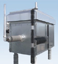
GE Vernova's FKGA8 generator circuit breaker is the ideal solution for large nuclear, coal or hydro power plants. The compact footprint of the single-phase design makes it suitable for new installations or retrofits of existing GCBs. It is equipped with a highly reliable spring-spring-operated mechanism per pole.
FKGA8 Generator Circuit Breaker
Designed for Power Plants from 700 to 1,500 MW
GE Vernova's FKGA8 generator circuit breaker is the ideal solution for large nuclear, coal or hydro power plants. The compact footprint of the single-phase design makes it suitable for new installations or retrofits of existing GCBs. It is equipped with a highly reliable spring-spring-operated mechanism per pole.
Advanced Architecture
Based on more than 40 years experience in providing generator circuits breakers with performances up to 1,500 MW, GE Vernova introduces the FKGA8 with well recognized and advanced architecture suitable for large power plants. The circuit breaker's main contacts are in air, separated from the arcing SF6 chamber. These contacts are therefore protected from the hot current breaking SF6 gases including contaminated particles and associated by-products, reducing premature aging of the equipment. Additionally the combination of the circuit-breaker and the disconnector functions avoids energy losses caused by conventional in-line disconnector.
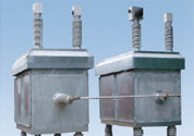
Enhanced Inspection and Maintenance
The architecture of the FKGA8 allows an easy observation of the main contacts throughout the GCB's periodic inspections. The value of having accessibility without dismantling of circuit breaker is enhanced by the fact that contact resistance measurement cannot alone be considered as reliable evidence (as notified by the latest IEC/IEEE 62271-37-013 ) of the contact health. By segregating the main contacts from the interrupting SF6 gas, the new FKGA8 provides also simple access from outside the breaker during a short, normally scheduled power plant shutdown.
Single-Line-Diagram
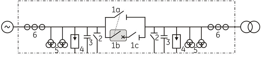
1) Circuit breaker with integrated air-disconnector 1a) Main contacts
1b) Arcing contacts
1c) Safety Visual Switch
1a + 1b) = Circuit breaker
1a + 1c) = Disconnector
2) Earthing switch
3) Capacitors
4) Surge arresters
5) Voltage transformers
6) Current transformers
Key Benefits
- Advanced architecture of circuit breaker reduces premature aging by relocating the main contacts outside of the SF6 environment
- Combination of circuit breaker and disconnector function minimizes energy losses
- Reduced SF6 volume of arcing chamber for lower environmental impact
- Reliable spring-spring-operated mechanism per pole
- Main contact's inspection and maintenance made easier and less time consuming
- Compact breaker size both for retrofits and new installations
Performance
| Ratings | Units | FKGA8 | ||||||||
|---|---|---|---|---|---|---|---|---|---|---|
| Rated max. voltage | kV | 33 | ||||||||
| Short-circuit breaking current | kA | Up to 210 | ||||||||
| Ambient air temperature limits | °C | -20 °C to +40 °C | ||||||||
| Busbar temperature limit/Enclosure temperature limit | °C | 90/70 °C | 105/80 °C |
| ||||||
| Frequency | Hz | 50 | 60 | 50 | 60 | |||||
| Max. rated nominal current* | ||||||||||
| - Indoor with ambient air 40 °C | A | 30,000 | 28,500 | 27,200 | 24,500 | |||||
| - Outdoor with ambient air 40 °C | A | 29,000 | 26,200 | 26,200 | 23,300 | |||||
| *Up to 40,000 A with IPB longitudal forced air cooling | ||||||||||
| FKGA8 Circuit Breaker | FKGA8 Integrated Air-Disconnector | MKG Earthing Switch | |||
|---|---|---|---|---|---|
| Rated peak withstand current | kApeak | 685 | 685 | 575 | |
| Rated short-time withstand current | kA | 250 | 250 | 210 | |
| Rated duration of short-circuit | s | 3 | 3 | 3 | |
Recommended Products & services
FKGA8 Generator Circuit Breaker
GE Vernova's FKGA8 generator circuit breaker is the ideal solution for large nuclear,...
View More