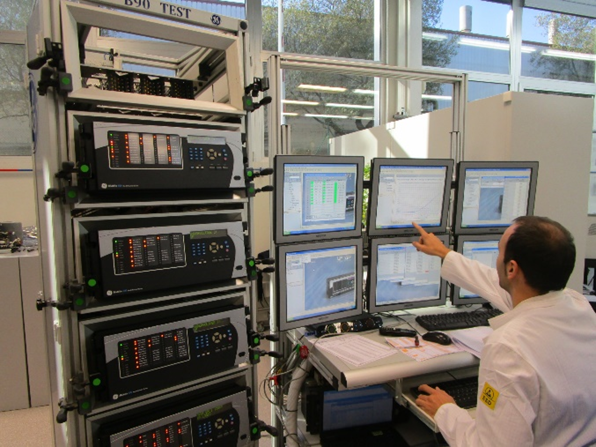
Real-Time Digital Simulation Services
Real-Time Digital Simulation (RTDS) has emerged as a crucial technology in the face of the evolving challenges that the electrical grid faces, such as the integration of distributed energy resources (DERs), better grid resilience, smart grid technologies, and the demand for electric vehicles (EVs). We support customers with our four dedicated RTDS laboratories to ensure reliable and robust grid operations during and after disruptive events through the following services:
Overview
The RTDS can simulate the electrical power system in real-time. Powerful processors work in parallel to simulate the output of an electrical system or network in terms of currents and voltages.
HIL Testing
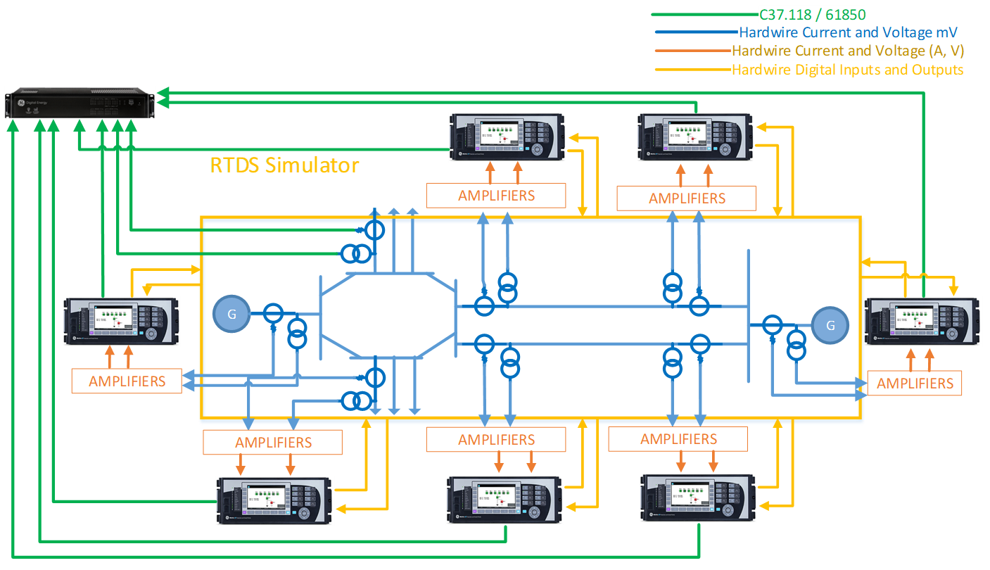
The RTDS is connected to voltage and current amplifiers which convert the RTDS command signals into voltages and currents. The relay’s outputs can be connected to the RTDS which can interpret these signals and take certain actions (open a breaker, calculate tripping time, etc.), thereby closing the loop. This can only be achieved with a real-time simulator.
The closed-loop interaction of the protection system with the network model provides insight on both the performance of the relay scheme as well as its effect on the power system. A simple schematic of HIL is shown below.
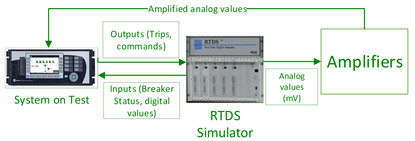
A model of the power system is implemented on the RTDS that includes the high-voltage components (e.g., lines, breakers, instrument transformers, power transformers, generators, etc.) plus the required protection and control functions not included in the equipment under testing.
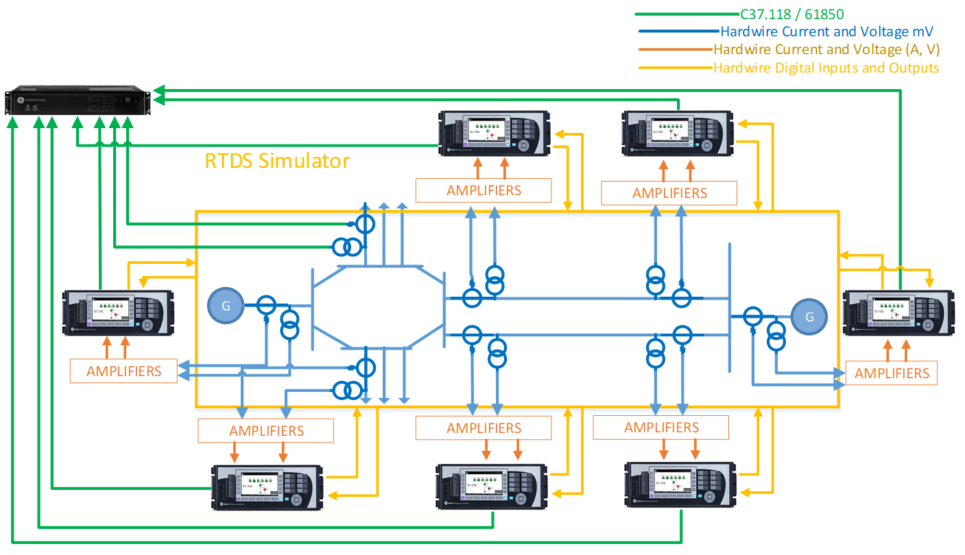
Illustrated below is a typical topology for WAMPAC testing through RTDS, where detailed models of the instrument transformers (CT, PT, and CVTs) provide signals to amplifiers that convert the values to real secondary values as if we were on a real power system. PMU and IEC 61850 sampled values can also be included as part the outputs of our system in tests for HIL. Digital inputs and outputs are also exchanged between relays.
Use Cases
Use Case 1 - Island Protection Implementation
Challenge: A customer needs to detect an islanding condition and identify events in the grid that could affect the point of interconnection (POI).
Value Added Proposition: Determine the parameters and methodology to trigger islanded identification. RTDS tests for validation purposes for loss of generation detection through sudden or cascade loss, loss of load detection through sudden or cascade loss, and trip to island from the external grid.
Benefits: Allow plant operation during islanding conditions through balance of load and generation.
Use Case 2 - Settings Audit
Challenge: A customer is facing unexpected protection tripping, impacting plant production. Undesired blackouts are costing $1M of lost profit per plant maloperation.
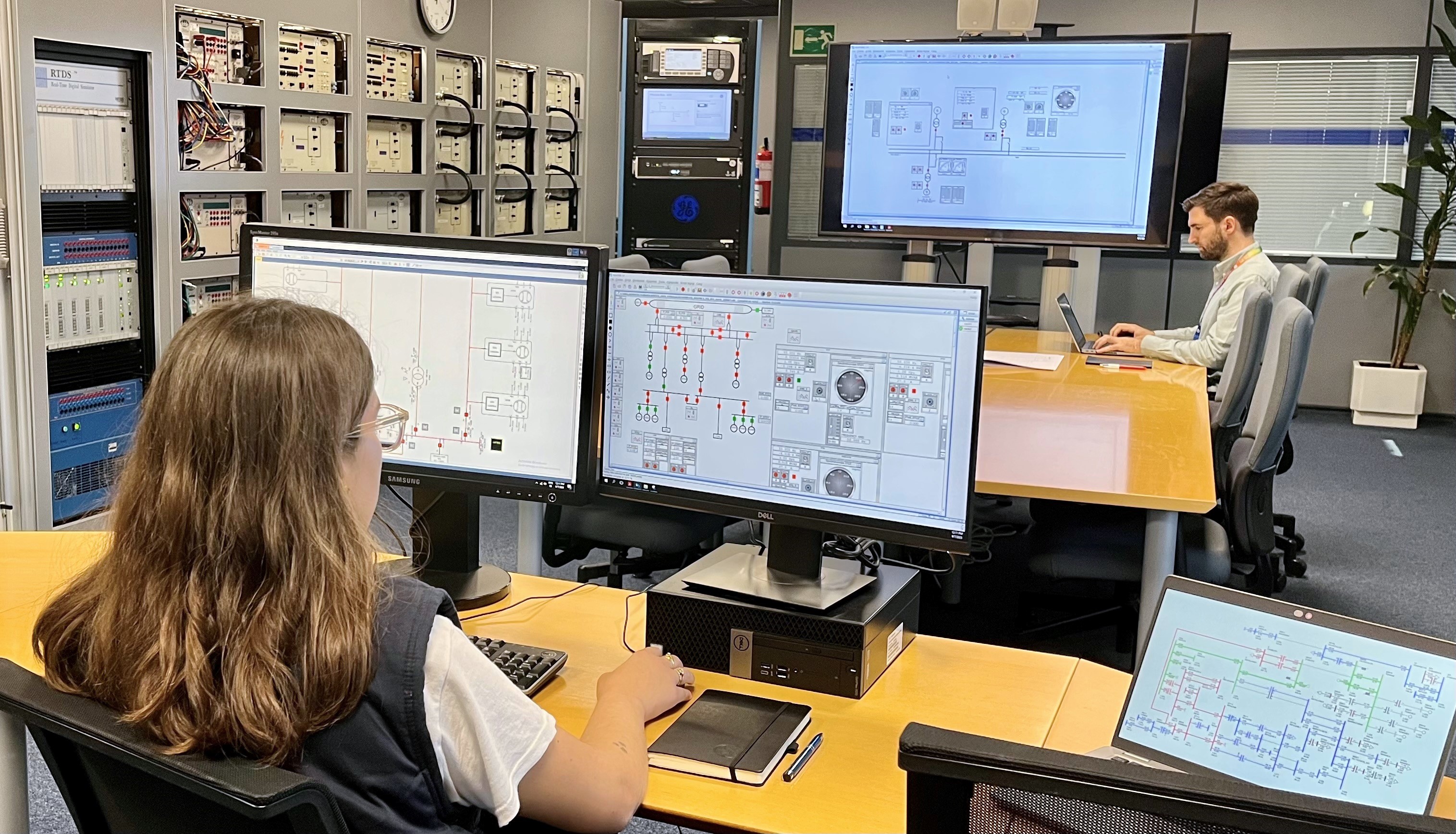
Value-Added Proposition: Existing settings are audited in an HIL environment with the same relays involved in plant operation. Multiple scenarios and faults are analyzed, and new setting proposals are tested on several cases when any finding is uncovered. A final report with findings and recommendations to improve setting coordination is delivered.
Benefits: Plant operation time is increased due to proper coordination, and time-to-repair is reduced through fast identification of the fault location. RTDS tests improved coordination between HV and MV sides. Some of the findings included miscoordination between bus coupler and feeder protection elements, phase undervoltage elements, and interlock inhibitions.
Use Case 3 - System Integrity Protection Scheme Validation
Challenge: System Integrity Protection Schemes are complex systems where multiple devices must be tested at the same time in the most realistic conditions due to their criticality in power system stability.
Value Added Proposition: RTDS tests become a mandatory requirement for factory acceptance test (FAT) to validate all dynamic test scenarios. Analog values from the electrical system are simulated, amplified, and hardwire to IEDs included in the SIPS, and additional information can also be sent directly from the test system to the SIPS central unit through PMU or IEC 61850 exchange, depending on the project design.
Benefits: These tests can highlight unforeseen scenarios and reduce commissioning time and minimize disruption to the operational network.
Recommended Products & services
Field Services
Our field service engineers are available to provide technical expertise on-site. With over 1,000 years of cumulative experience in protection and control, substation automation, monitoring and diagnostics, and industrial communications, we work with our customers to understand their needs and requirements, and work relentlessly until business objectives are met.
Recommended Products & services
Engineering Services
Our engineering services team provides a wide range of capabilities to assist you with your power protection, substation automation, and monitoring and diagnostics challenges.
We provide end-to-end solutions to support your project needs. From new installations to understanding the best way to upgrade an existing system, our engineering team has been trusted to analyze, design, and implement modern power systems with a broad range of engineering services that includes:
Overview
IED configuration and pre-loading
These services entail configuration of Grid Automation and third-party P&C devices as per agreed settings and functionality.
Settings can be determined by our calculation of settings and studies or can be supplied by the customer.
Under request, the files can also be uploaded into the customer devices and tested before shipping or installation. Additionally, functional testing for final settings can be tested and reported.

Communication mapping
Communication capabilities of current relays are extensive and complex architecture networks are needed in existing substations.
Grid Automation experts can help to unleash communication capabilities within already installed devices, support customers in new deployments, or improve communications architecture and ensure efficient use of network traffic.
Our support can be as simple as helping to configure customer signal mappings, or complex IEC 61850 device integrations. Any protocol supported by our products can be managed.
FAT
The Grid Automation business offers the technical expertise to provide a reliable factory acceptance test, no matter if it is be carried out on our premises, or at third-party installations.
Before material delivery, our FAT support ensures functionality, quality, and integrity with our comprehensive checking process, guaranteeing that the equipment performs as expected under the testable range of foreseeable conditions.
Busbar Engineering Solution
GE Vernova's Busbar Differential System provides fast and secure low impedance bus protection for reconfigurable LV, HV, and EHV busbars. This integrated solution is comprised of engineering, design, assembly, wiring, testing, and commissioning support for protection, control, and automation applications.
Depending on the nature of the protection, we differentiate between three different types of busbar differential projects:
- Busbar Differential Low-Impedance Centralized Protection System (B30/B90/P746/P747)
- Busbar Differential Low-Impedance Distributed Protection System (B30/P741/2/3 Agile)
- Differential High-Impedance Protection Systems (P145/P14NB)
Distributed Busbar Protection
The B30, a member of the UR family, provides busbar protection for up to 16 feeders with six differential zones. Communication between the bay and central units is done using process bus (IEC 61850-9-2LE) or standard (IEC 61869) protocols, and offers a large, full color LCD display. It can also be used for centralized protection of MV substations requiring busbar, breaker fail, feeder phase/neutral/ground overcurrent, and under/overvoltage protection.
Centralized Busbar Protection
Comprehensive and scalable bus and breaker fail protection for LV, HV, and EHV busbars. The B90, a member of the UR family, supports multi-section busbars schemes of up to 24 feeders and six zones, and offers a large, full color LCD display.
Key Benefits
- High-speed differential protection algorithm for sub-cycle trip times of 0.75 power cycle with CT saturation detection with only 2ms of saturation-free current.
- Multiple ethernet ports for station and process bus with advanced IEC 61850 Ed. 1 and Ed. 2 certified implementation, complete settings via SCL files and highly flexible process bus support (IEC 61850-9-2LE or IEC 61850-9-2 hard fiber) ensures interoperability, improved device management, and reduced cost of ownership.
- Routable GOOSE (R-GOOSE) enables GOOSE messages going beyond the substation.
- Application flexibility with multiple I/O options including high density I/O, programmable logic, modularity, and specific customization.
- Advanced cybersecurity features (CyberSentryTM) that help meet modern industry requirements.
- An integrated large, full color display provides real-time visualization and control of the protected bay via a bay mimic, as well as annunciator functionality and graphical visualization of phasors.

Automatic Transfer Schemes
Electrical processes are becoming more critical every day. Whether these processes are industrial or commercial, uninterrupted power supply is vital. In order to provide more reliable power supply, the power system can alternate sources to different bus bars. An Automatic Transfer Scheme (ATS) is the process of transferring the load of a busbar to another to ensure process continuity.
The ATS helps ensure the continuity of critical processes whose shutdown would result in unwanted economic and safety consequences. Transferring motor buses are specifically challenging due to the inertia forces and transients that exist in motors.
The Automatic Transfer and Restoration Scheme combines distributed protection, control, and ATS capabilities in a cost-effective package. Depending on your project-specific requirements for inputs/outputs, it can be performed on our SR850, F650, or P40x relays.
Key Benefits
- Control of multiple breakers
- Use of IEC61850 standard: reduction in cabling and commissioning costs
- Interlocking can be programmed in logic for a further reduction in costs
- Pre-built and/or custom logic
- Fast transfer, residual voltage transfer, or other customer-specific schemes
- Manual changeover can be implemented for planned start-ups, shutdowns, or changeover of power
- Make-before-break or break-before-make
- Automatic restoration with healthy voltage and synchrocheck criteria that minimizes the outage time and helps operators simplify the recovering process


Main-Main
This configuration can be found in thermal power generating stations. The example shows a hard-wired solution.

Main-Tie-Main
This type of configuration is mainly used in industrial plants. The example shows a solution with GOOSE 61850 inter-relay communication.

Main-Tie-Main with Emergency Diesel Generator (EDG)
The Main-Tie-Main configuration can be improved by adding an emergency generator that would operate in case of loss of power on both main sources. The example shows a solution with GOOSE 61850 inter-relay communications.
Digital Substation Standardization
The transition to digital substations has emerged as a transformative approach to enhance operational efficiency, flexibility, and reliability. Digital substation standardization is a critical process that defines consistent protocols, interfaces, and architectures for the seamless integration of intelligent electronic devices (IEDs), communication systems, and control infrastructure. Digital substation standardization is essential for driving the adoption and implementation of advanced technologies in power system networks.
Benefits
Our team possesses extensive expertise and experience in digital substation standardization, offering comprehensive solutions tailored to the unique needs of power system networks, including:
- A deep understanding of international standards and protocols relevant to digital substations, such as IEC 61850, IEEE 1588, and IEC 62351.
- Network architecture designed based on the substation architecture and topology for digital substations. We consider factors such as network topology, redundancy requirements, scalability, and system performance. By leveraging standardized architecture, such as the process bus and station bus concepts, we ensure efficient data exchange, streamlined control, and seamless integration of devices and systems.
- Our team has proficiency in integrating and configuring IEDs from various vendors within digital substations. We ensure that devices adhere to standardized communication profiles, data models, and protocols, enabling seamless interoperability and reliable data exchange.
- We prioritize cybersecurity in digital substations, implementing standardized security mechanisms, including authentication and access control.
- Test procedures for FAT, Site Acceptance Tests (SAT) and maintenance are provided based on IEC61850 standard, including simulation and test modes.


Use Case
Challenge: Assure a new standard for digital substation design and provide new communications networks and architecture on digital substations.
Value Added Proposition: Design and implementation of standardized schematics for network architecture and communication signals exchange. .scd and .cid template file generation.
Benefits: A standardized solution for three typical topologies, making them more efficient on digital substation implementation. Closure of technology gap for customer employees.
Remedial Action Schemes
Remedial Action Schemes (RAS) are a type of Wide-Area Protection Scheme, also known as Special Protection System (SPS) or System Integrity Protection Scheme (SIPS). RAS systems can detect disturbances in one part of an interconnected network that could result in interconnection overloading, under/over frequency conditions, and under/ overvoltage scenarios, and remediates these situations using pre-defined protection and control actions.
We support customers with the following services:
- Design and implementation of SIPS
- Defining RAS requirements
- System stability studies to identify contingencies and remedial actions
- Technical solutions and communication system architecture
- Solution validation including acceptance testing via advanced testing and result analysis
- Automatic data collection and results analysis from Grid Automation business and third-party devices
- System integration of the RAS system components
- Support during the commissioning of RAS components

Key Benefits
- Automatically disconnect generators or the load in the event of an unexpected loss of service of a transmission line to prevent system overloads.
- Improve system reliability by preventing power system outages.
- Increase transmission capability when building a new transmission line is not possible.
- Meet system operator mandates or system requirements.
Recommended Products & services
Consulting Services
Our team specializes in providing a comprehensive range of consulting services for power systems. With expertise backed by years of experience, we deliver in-depth analysis, expert recommendations, and innovative solutions. Count on us to deliver comprehensive insights, detailed reports, and expert recommendations to assist you in enhancing the performance, reliability, and safety of your power systems. Whether you need assistance with designing new systems, upgrading existing ones, or resolving specific issues, our consulting services deliver a holistic approach.
Load Flow or Power Flow Study
Load flow, also known as power flow, is a crucial analysis conducted in power system engineering to assess the steady-state performance of an electrical network. It helps determine how power is transmitted and distributed across the system, ensuring proper voltage regulation, improved power transfer, and reliable operation. The Load Flow Study considers the active power (real power) and reactive power (imaginary power) flows within the network. By simulating different operating conditions and loads, it provides critical information on voltage levels, power losses, line loading, and equipment capabilities. This data assists in system planning, operation, and expansion decisions.
Benefits
- Provides an overview of the system in a steady state
- Aids in system planning and expansion
- Load balancing and loss minimization
- Assessment of the voltage levels in the system
- Enhances the active and reactive Power flow in the network

Short Circuit Study
A Short Circuit Study, also known as a Fault Study or Fault Analysis, is a critical analysis performed in power system engineering to assess the behavior and response of an electrical network under short circuit conditions. It involves calculating fault currents, analyzing fault levels, and determining the impact of faults on equipment, protection systems, and overall system stability.
The primary objective of a Short Circuit Study is to ensure that the system can safely withstand and quickly recover from short circuits without causing extensive damage to equipment, personnel safety hazards, or prolonged power outages. The study helps identify potential areas of concern and enables engineers to design and implement appropriate protection measures.
Benefits
- Enables appropriate equipment selection
- Aids in effective protective system design
- Ensures proper coordination of protective devices
- Facilitates risk assessment and mitigation


Protection Coordination Study
Protection coordination is a critical aspect of electrical power system design and operation. A Protection Coordination Study involves analyzing the protective devices such as relays, fuses, and circuit breakers, to ensure their proper coordination and timely response to faults. By coordinating protection settings, engineers can minimize system downtime, mitigate the impact of faults, and enhance overall system reliability.
The study aims to minimize equipment damage and system downtime by ensuring that the protective devices closest to the fault isolate the faulted area while keeping the rest of the system operational.
Benefits
- Ensures selectivity of protective devices
- Increased reliability of the network
- Enhance equipment protection
- Compliance verification

Arc Flash Study
Arc flash incidents pose significant risks to personnel working with or around electrical equipment. An Arc Flash Study, also known as an Arc Flash Hazard Analysis, is a critical process in assessing and mitigating the hazards associated with electrical arc flashes. By analyzing the electrical system, identifying potential arc flash hazards, and implementing appropriate safety measures, engineers can protect workers, prevent accidents, and ensure compliance with safety regulations.
Benefits
- Risk reduction
- Implementation of appropriate safety measures
- Improved worker safety
- Compliance with regulations
Outcomes
- Incident energy analysis
- Defined arc flash boundary
- Mitigation strategies to reduce arc flash
- Recommendations on PPE


Stability Study
Stability is a crucial aspect of power system operation and planning. Power system stability studies are conducted to assess the dynamic behavior and response of the system under various operating conditions. These studies analyze the system's ability to maintain stable and secure operation following disturbances such as faults, sudden load changes, or switching actions.
The primary objective of a stability study is to ensure that the power system can withstand and recover from disturbances without experiencing significant voltage or frequency deviations, stability limits violations, or even blackouts. By conducting stability studies, stakeholders can identify potential stability issues, develop appropriate mitigation strategies, and enhance the system's overall reliability and performance.
Benefits
- Stability assessment
- Study system reliability and security
- Aids in system planning and expansion
- Contingency analysis and emergency preparedness
- System protection evaluation
Outcomes
- Assessment of stability and identification of stability issues
- Calculation of critical clearing time and dynamic response

Motor Acceleration Study
Motor Acceleration Simulation Studies have become an essential tool in the field of engineering, enabling designers to analyze and select the suitable motor for their application in conjunction with their existing network. By leveraging mathematical models and advanced simulation techniques, engineers can gain valuable insights into motor behavior and enhance acceleration performance.
The primary objective of the Motor Acceleration Study is to determine the voltages, currents, and starting times involved when starting large motors or a group of motor, either sequentially or simultaneously.
Benefits
- Improved motor selection
- Improved motor performance
- Improved system stability for islanded systems
- Enhanced operational efficiency
Outcomes
- Motor performance analysis
- Determination of acceleration time
- Power system impact assessment

Power Quality Study
Power quality refers to the characteristics of electrical power that determine its suitability for reliable operation of electrical equipment. A Power Quality Study involves assessing and analyzing various parameters of the electrical supply to identify any deviations from desired standards. The study aims to understand the causes of power quality issues, evaluate their impact on the electrical system, and implement appropriate measures to mitigate them.
Benefits
- Improved equipment reliability
- Enhanced equipment performance
- Better energy efficiency
- Enhanced safety
- Compliance with international standards and local regulations
The following are some power quality standards:
- IEEE 519: Provides guidelines for harmonic control in electric power systems.
- IEC 61000: Specifies limits and measurement techniques for electromagnetic compatibility (EMC), including power quality.


EMTP Study
Electromagnetic Transients Program (EMTP) is a software tool widely used in the analysis and simulation of transient phenomena in power systems. It is a computer-based simulation program that provides a platform for studying electromagnetic transients, such as voltage and current waveforms, in electrical networks. EMTP studies are focused on analyzing and simulating transient events, while RMS studies primarily analyze steady-state conditions. The EMTP analysis allows engineers to model and analyze the behavior of complex power system components and their interactions during transient events.
Benefits
- Enables the simulation of high-frequency transient phenomena with high accuracy, considering the nonlinear behavior of power system components, electromagnetic interactions, and system dynamics
- Effective in studying the impact of switching operations
- Allows for the modeling and analysis of lightning and surges
- Assists in understanding the impact of integrating renewable energy sources
- Aids in identifying potential problems and developing mitigation strategies
- Aids in sizing of equipment and protective devices
- Provides insights on system insulation coordination
- Allows users to vary component parameters, system conditions, and operating scenarios to study their impact on system behavior

Grid Compliance Study
Grid compliance refers to the adherence to technical requirements, standards, and regulations specified by grid codes. Grid codes define the rules and specifications for connecting power generation and load facilities to the grid, ensuring safe, reliable, and efficient operation of the power system. Grid codes vary regionally due to a range of factors including grid infrastructure, network characteristics, renewable penetration, generation mix, state-of-the-art technologies, grid stability, voltage control, frequency regulation, and institutional compliance. These studies aim to assess the behavior of renewable generation and distributed energy resources (DERs) under various operating conditions, identify potential grid integration issues, and recommend appropriate measures for compliance with specific country grid codes.
Grid compliance studies for renewable generation and DERs offer several benefits:
Benefits:
- Ensure grid stability and integrity
- Regulatory compliance
- Compliance to power quality
- Improved safety and fault management


Grid Integration Study
A Grid Integration Study is a comprehensive analysis conducted to assess the seamless integration of renewable generation and DERs into the existing power system. As the world transitions towards a more sustainable energy future, incorporating renewable energy sources and DERs, such as solar photovoltaics (PV), wind turbines, energy storage systems, and demand response into the grid becomes essential. A Grid Integration Study aims to evaluate the technical, economic, and operational aspects of integrating these resources into the power system while ensuring stability, reliability, and optimal performance.
These studies are highly customized to address the specific concerns of a particular power system. Generally, these studies involve the use of modeling approaches that fall into three main categories: capacity expansion, production cost, and power flow analyses. While an ideal Grid Integration Study incorporates all three types of analyses, many studies focus on just one or two methods.
Benefits
- Assesses upcoming generation and transmission portfolios to achieve renewable energy targets at reduced costs while maintaining reliability objectives.
- Simulates the operation of the power system under different future renewable energy-penetration scenarios and at different timescales.
- Identifies reliability constraints associated with different renewable energy scenarios.
- Determines the relative cost of integrating high levels of variable renewable energy.