NGV Voltage Relay
The type NGV relay is a high-speed relay designed for calibration on decreasing voltage (drop-out), or increasing voltage (pick-up) and may be continuously energized at rated voltage. The NGV19 is a special relay available for application as a battery monitor.
NGV Voltage Relay
The type NGV relay is a high-speed relay designed for calibration on decreasing voltage (drop-out), or increasing voltage (pick-up) and may be continuously energized at rated voltage. The NGV19 is a special relay available for application as a battery monitor.
Recommended Products & services
NGV Voltage Relay
The type NGV relay is a high-speed relay designed for calibration on decreasing voltage...
View MoreIFCV TOC Relay with Voltage Restraint
The Type IFCV relays are draw out, induction disc time-overcurrent relays having voltage restraint and inverse time characteristics.
Applications
- System fault backup protection
Protection and Control
- Time O/C unit with voltage restraint
IFCV TOC Relay with Voltage Restraint
The Type IFCV relays are draw out, induction disc time-overcurrent relays having voltage restraint and inverse time characteristics.
Applications
- System fault backup protection
Protection and Control
- Time O/C unit with voltage restraint
Recommended Products & services
IAC Time-overcurrent Relay
Type IAC relays are used in the protection of industrial and utility power systems...
View More
IFCV TOC Relay with Voltage Restraint
The Type IFCV relays are draw out, induction disc time-overcurrent relays having voltage...
View More
IFC Time-overcurrent Relay
Type IFC relays are used for the protection of industrial and utility power systems...
View MoreIAC Time-overcurrent Relay
Type IAC relays are used in the protection of industrial and utility power systems against either phase or ground overcurrent. They are single phase (although some models contain more than one unit), non-directional, current sensitive, AC devices. The basic operating mechanism (the time unit) produces one of several available operating characteristics. The operating time is inversely related to operating current which permits close coordination with other protective devices.
IAC Time-overcurrent Relay
Type IAC relays are used in the protection of industrial and utility power systems against either phase or ground overcurrent. They are single phase (although some models contain more than one unit), non-directional, current sensitive, AC devices. The basic operating mechanism (the time unit) produces one of several available operating characteristics. The operating time is inversely related to operating current which permits close coordination with other protective devices.
Recommended Products & services
IAC Time-overcurrent Relay
Type IAC relays are used in the protection of industrial and utility power systems...
View More
IFCV TOC Relay with Voltage Restraint
The Type IFCV relays are draw out, induction disc time-overcurrent relays having voltage...
View More
IFC Time-overcurrent Relay
Type IFC relays are used for the protection of industrial and utility power systems...
View MoreIFC Time-overcurrent Relay
Type IFC relays are used for the protection of industrial and utility power systems against either phase or ground overcurrent. They are single-phase, non-directional, current sensitive AC devices. The basic operating mechanism (the time unit) produces one of several available operating characteristics with operating time inversely related to operating current to permit coordination with other protective devices. It consists of a magnetic-core operating coil, an induction disk, damping magnet, and a mechanical target.
IFC Time-overcurrent Relay
Type IFC relays are used for the protection of industrial and utility power systems against either phase or ground overcurrent. They are single-phase, non-directional, current sensitive AC devices. The basic operating mechanism (the time unit) produces one of several available operating characteristics with operating time inversely related to operating current to permit coordination with other protective devices. It consists of a magnetic-core operating coil, an induction disk, damping magnet, and a mechanical target.
Recommended Products & services
IAC Time-overcurrent Relay
Type IAC relays are used in the protection of industrial and utility power systems...
View More
IFCV TOC Relay with Voltage Restraint
The Type IFCV relays are draw out, induction disc time-overcurrent relays having voltage...
View More
IFC Time-overcurrent Relay
Type IFC relays are used for the protection of industrial and utility power systems...
View MoreRRTD Remote RTD Module
The Remote RTD Module provides additional RTD temperature metering capabilities for other relays such as the Multilin M60, 369 or 859.
RRTD Remote RTD Module
The Remote RTD Module provides additional RTD temperature metering capabilities for other relays such as the Multilin M60, 369 or 859.
RMIO: Remote Module I/O
Remote monitoring of RTDs for metering and protection
The Remote I/O Module provides RTD temperature metering capabilities for the Multilin 339 motor protection relay.
The remote RTD Module provides additional protection for motor applications by monitoring the temperature of key components in the motor. All RTD’s settings are completely configurable via the 339 motor relay and via EnerVista Software.
Agile P253
Motor Protection
Agile P253
Motor Protection
Recommended Products & services
Agile P24xM - Legacy
Motor Management
Motor Protection & Control
The P24xM Series (P24NM, P24DM) deliver field proven protection, measurement and control algorithms built from GE Vernova’s P40 Agile range of protective devices.
The P24NM and P24DM devices offer multi-stage independent protection elements including a variety of curves in four setting groups. Machine thermal imaging monitoring, start supervision, and circuit breaker condition monitoring ensure maximum process uptime and system reliability.
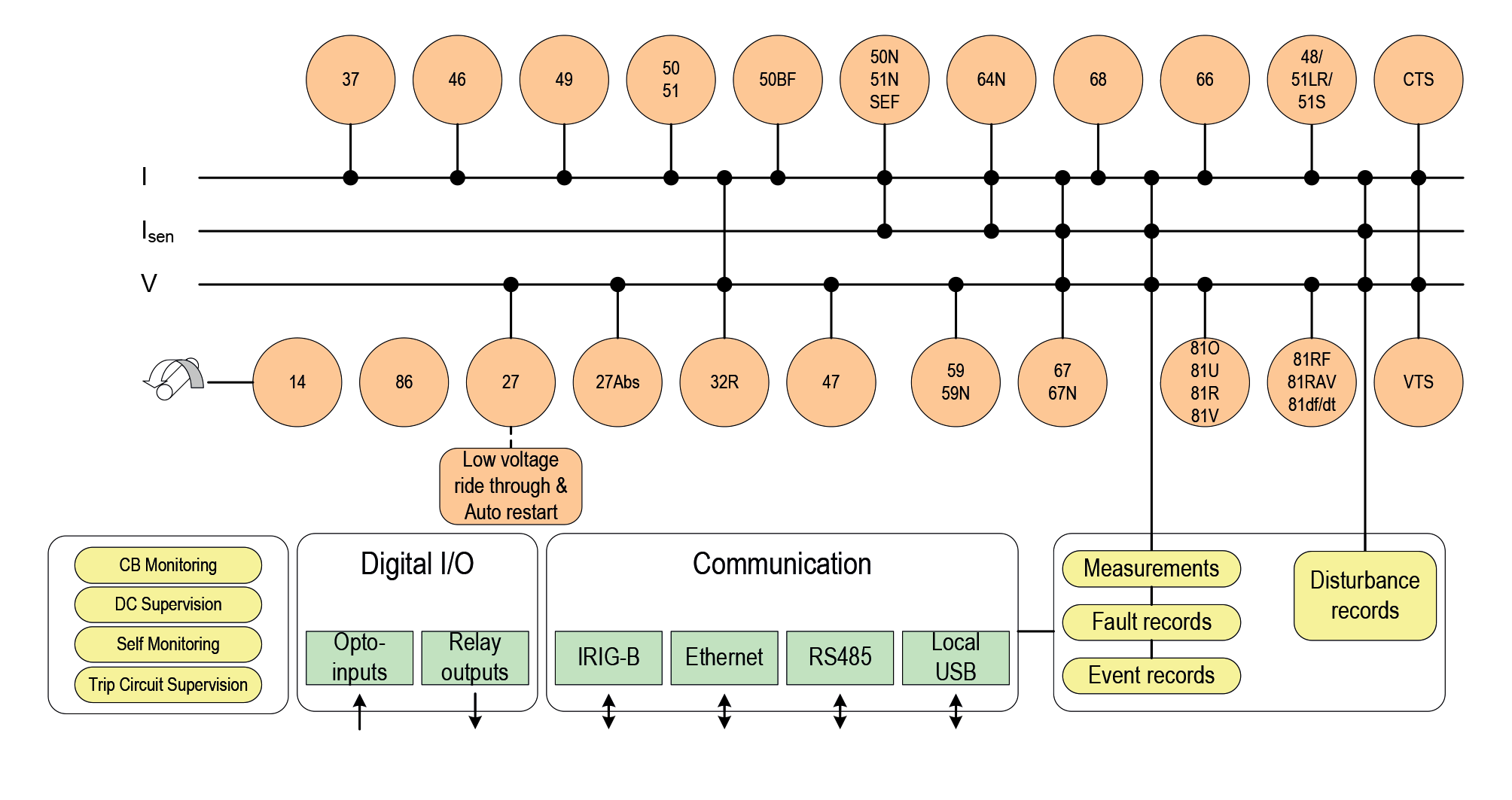
P24xM Functional Diagram
Communications
The P24xM Series offers flexible and redundant communications options, simplifying device integration into SCADA or DCS systems.
Two communication ports are standard - a rear port providing remote communications and a front port for local operators. The front USB port allows the programming of settings, configuration of the programmable scheme logic, extraction and viewing of event, disturbance and fault records, viewing of measurements and the instigation of control functions.
The P24xM series supports the following advanced communication protocols:
- Courier / K-Bus
- Modbus
- IEC 60870-5-103
- DNP 3.0 (RS485 serial or Ethernet)
- IEC 61850 (100 Mbit/s Ethernet)
IEC 61850 or DNP 3.0 over Ethernet are available when the optional Ethernet port is ordered in the 30TE and 40TE models. Redundant Ethernet protocol PRP, HSR and RSTP are also available in dual RJ45 or dual fiber. The copper physical link option uses RJ45 connectors, the fiber option uses LC connectors. IEC 61850 offers high-speed data exchange, peer-to-peer communication, reporting, disturbance record extraction and time synchronization. To help smooth transition from the existing protocol to the IEC 61850 protocol, the P40 Agile relay had been designed to provide concurrent Courier, Modbus or DNP3 on the RS485 while provide IEC 61850 over Ethernet port.
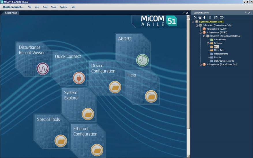
MiCOM S1 Agile Software Toolsuite
- Configuration file creation and management, following the substation topology
- Ethernet and IEC 61850 configuration, including SCL import and export
- Programmable logic, menu text and IDMT curve profiles
- Setting conversion to the new P40 Agile IEDs.
- Events and disturbance record extraction and viewing
- Embedded product selector
- Full successor to Micom S1
- Zero or minimal training to move from S1 Studio to S1 Agile
S1 Agile is the truly universal IED engineering toolsuite. No-longer are separate tools required for redundant Ethernet configuration, scheme operational dashboards, programmable curve profiles or automatic disturbance record extraction – all applications are embedded.
MiCOM S1 Agile Universal IED Engineering Toolsuite
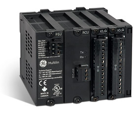
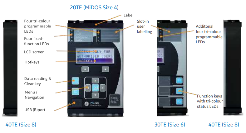
Flexible Hardware Platform
- Space-saving 4U height and 20TE (4"), 30TE (6") or 40TE (8") case sizes
- A front USB port and a rear RS485 port
- Power-up diagnostics and continuous self-monitoring
- Wide choice of opto-isolated binary inputs and output relays
- N/O (form A) and N/C (form B) watchdog contacts
- Field upgradeable to change the relay model avoiding costly hardware change via firmware upgrade
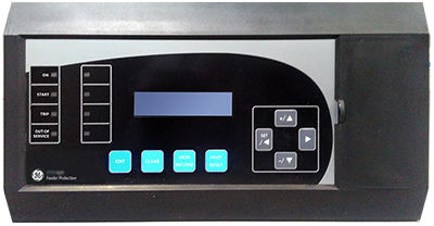
The front-panel interface allows direct IED interaction. . Integrated user function keys and tri-color programmable LEDs provide a cost-effective solution for control and annunciation.
Intuitive Front Panel Interface
Recommended Products & services

Motor Protection
GE Vernova’s motor protection systems use advanced thermal modeling to provide...
View MoreMM300
Low voltage motor management
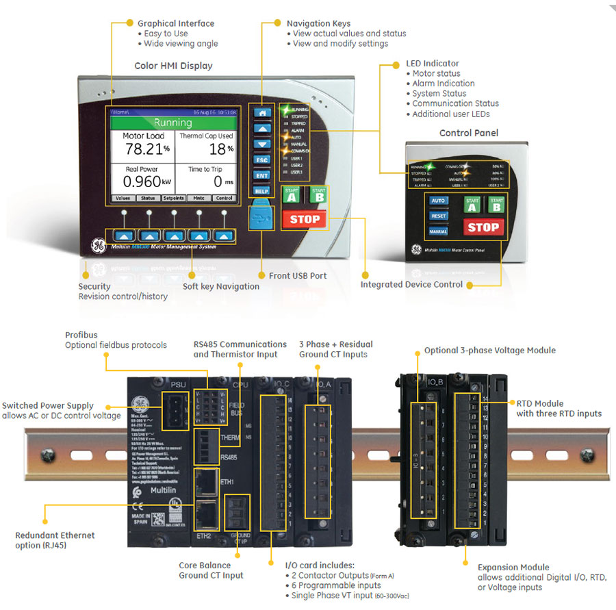
The MM300 integrates protection, control, automation, metering, diagnostics and multiple communication protocols in a rugged compact device for low voltage motor applications. Designed for NEMA and IEC Motor Control Centers, the MM300 delivers superior protection and control to extend equipment life and maximize process uptime.
MM300
Low voltage motor management
The MM300 integrates protection, control, automation, metering, diagnostics and multiple communication protocols in a rugged compact device for low voltage motor applications. Designed for NEMA and IEC Motor Control Centers, the MM300 delivers superior protection and control to extend equipment life and maximize process uptime.
Overview
The MM300 integrates protection, control, automation, metering, diagnostics and multiple communication protocols in a rugged compact device for low voltage motor applications. Designed for NEMA and IEC Motor Control Centers, the MM300 delivers superior protection and control to extend equipment life and maximize process uptime.
Two variants are available within the MM300 range:
- MM300 Enhanced
- MM300 (DeviceNet Application) Manufacturing for the MM300 has been Discontinued. Please contact GE Vernova for availability. As an alternative, please refer to MM300 Enhanced.
The MM300 Enhanced supports higher processing capability which enables advance communication options including latest IEC61850 Ed.2 protocol, Ethernet redundancy according to IEC62359-3 (PRP/HSR) ensuring higher availability and zero loss of data. Other communication options include Modbus serial/TCP & Profibus. The Protection, Monitoring & Control capability has been greatly enhanced with support for Event, Fault, Disturbance recorder, Data logger, Motor Health Records, Motor Learned Data etc. The MM300 Enhanced delivers a host of cybersecurity features that help operators to comply with NIS and NERC CIP guidelines, or other security regulations.
The MM300 Enhanced is built upon the same powerful shared platform as the P40 Agile Enhanced and 8 Series. This encourages mixed usage in projects without additional training needs.
The MM300 (DevcieNet Application) supports standard Motor Protection, Monitoring & Control options. The device is fully scalable, supports various digital input/output options to suit application needs. The device support host of industry protocols including DevicenNet. Other protocols supported include Modbus serial/TCP & Profibus. Only single Ethernet interface is supported as an ordering option.
Protection & Control
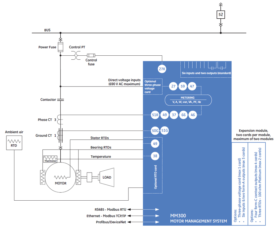
The MM300 Enhanced is a digital motor protection and control system, designed for Low Voltage motor applications. Flexible and powerful, the MM300 Enhanced’s protection can be scaled to the specific requirements of your system.
Functional block diagram
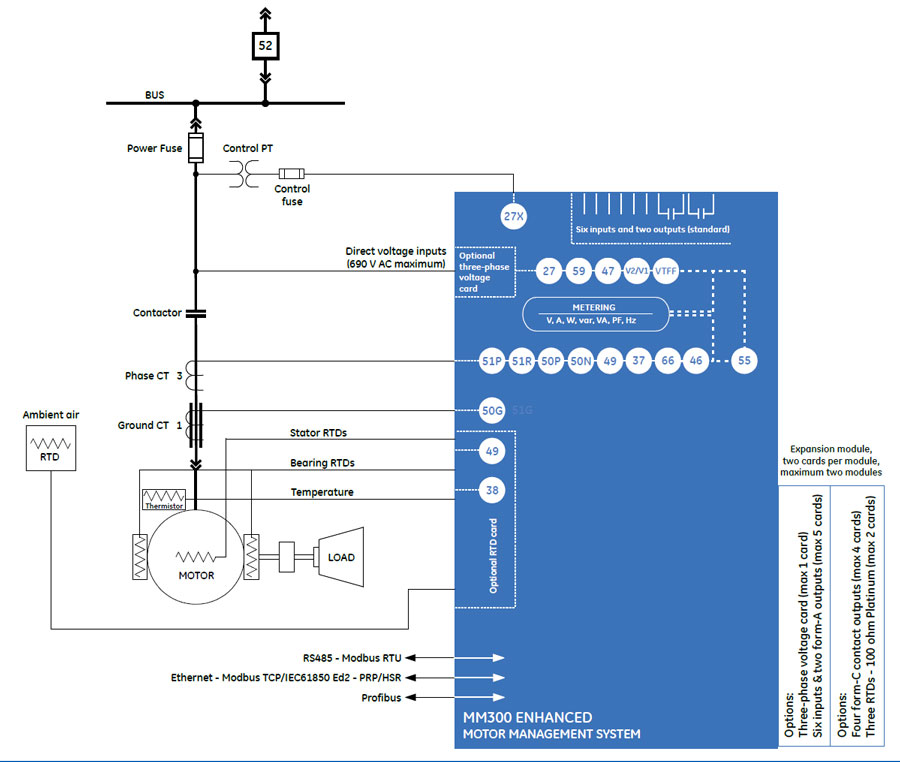
ANSI Device Numbers & Functions
| DEVICE NUMBER | FUNCTION |
|---|---|
| 27AUX | Undervoltage - Auxiliary Input |
| 27 | Undervoltage - Three Phase |
| 37 | Undercurrent/Underpower |
| 38 | Bearing Temperature RTD |
| 46 | Current Unbalance |
| 47 | Voltage Phase Reversal |
| 49 | Thermal Overload |
| 50P | Phase Instantaneous Overcurrent |
| 51P | Phase Time Overcurrent |
| 50G | Ground Instantaneous Overcurrent |
| 50N | Neutral Instantenous Overcurrent |
| 51R | Locked/Stalled Rotor/Mechanical Jam |
| 55 | Power Factor |
| 59 | Overvoltage - Three Phase |
| 60VTS | Fuse Failure |
| 66 | Starts/Hour & Time Between Starts |
Key Features
- Metering - current, voltage, power, energy, frequency, power factor, RTD, Thermistor
- Oscillography – analog values at 32 samples/cycle and digital states
- Event Recorder - Up to 1024 time tagged events with 1ms resolution
- Fault recorder (up to 5)
- Motor Start records
- Last Trip data
- Data logger
- Advanced Motor Health report
- Advanced Device Health diagnostics
Monitoring & Metering
The MM300 Enhanced includes high accuracy metering for all AC signals, voltage, current, power metering, and temperature all available options. Current and voltage parameters are available as total RMS magnitude and angle
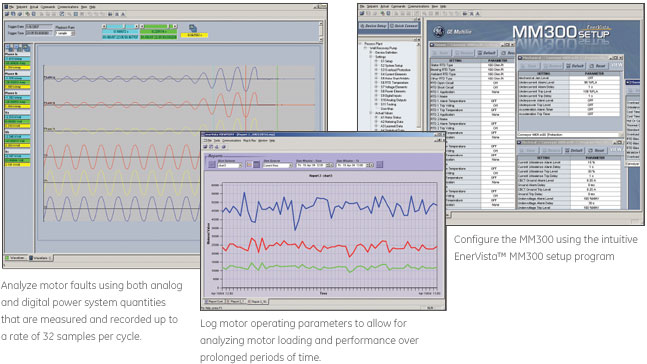
 Motor faults analysis using both analog and digital power system quantities that are measured and recorded up to a rate of 32 samples per cycle.
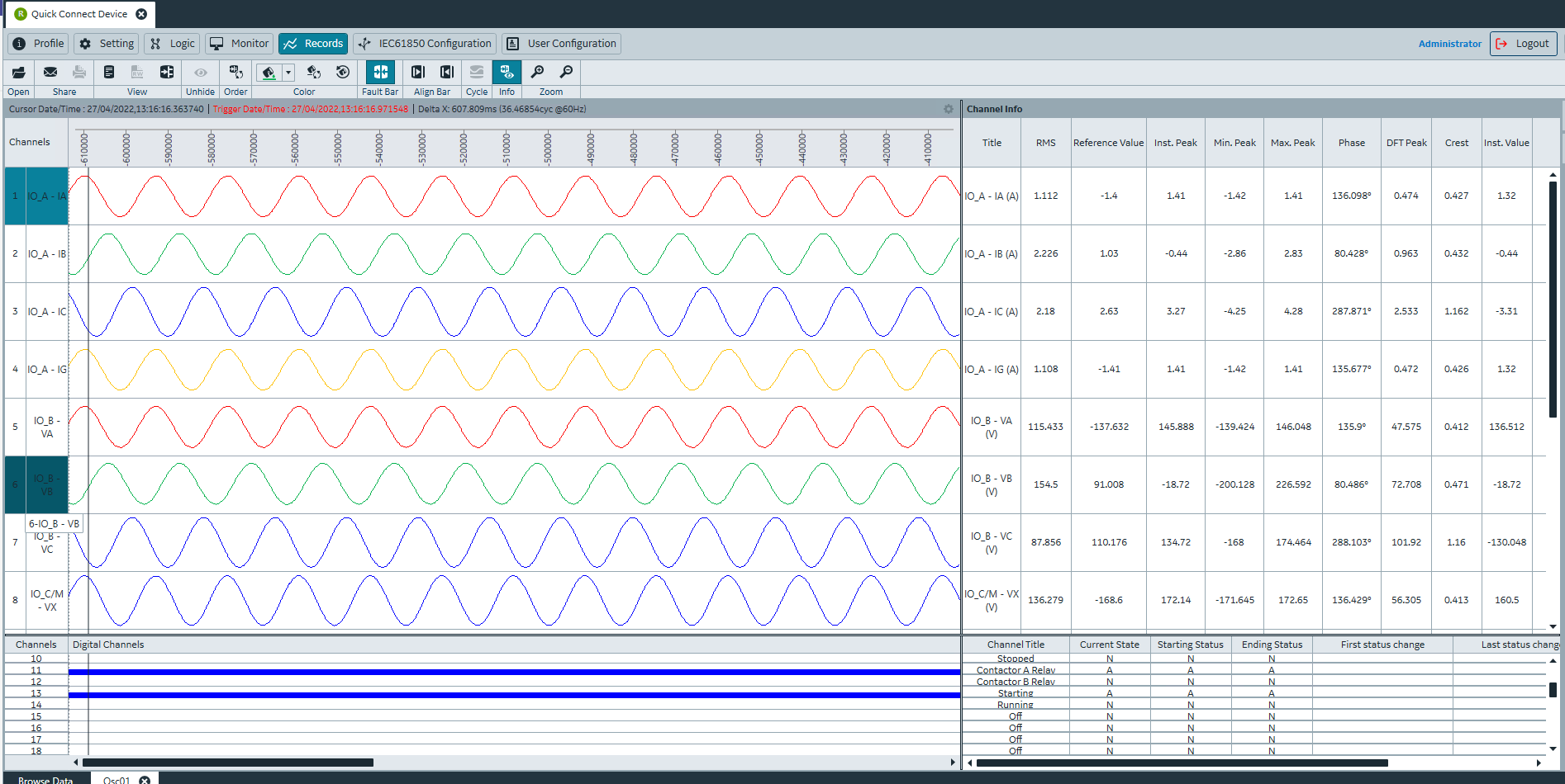
The MM300 Enhanced provides motor start recording in COMTRADE file format. The recording includes thermal profile, phase and ground currents & voltages, current unbalance, real, reactive, and apparent power, frequency, and motor status.
 Motor Start Record showing motor operating conditions during starts
The MM300 Enhanced’s powerful I/O and programmable FlexLogic options offer advanced automation control, reducing the need for additional programmable controllers or discrete control relays.
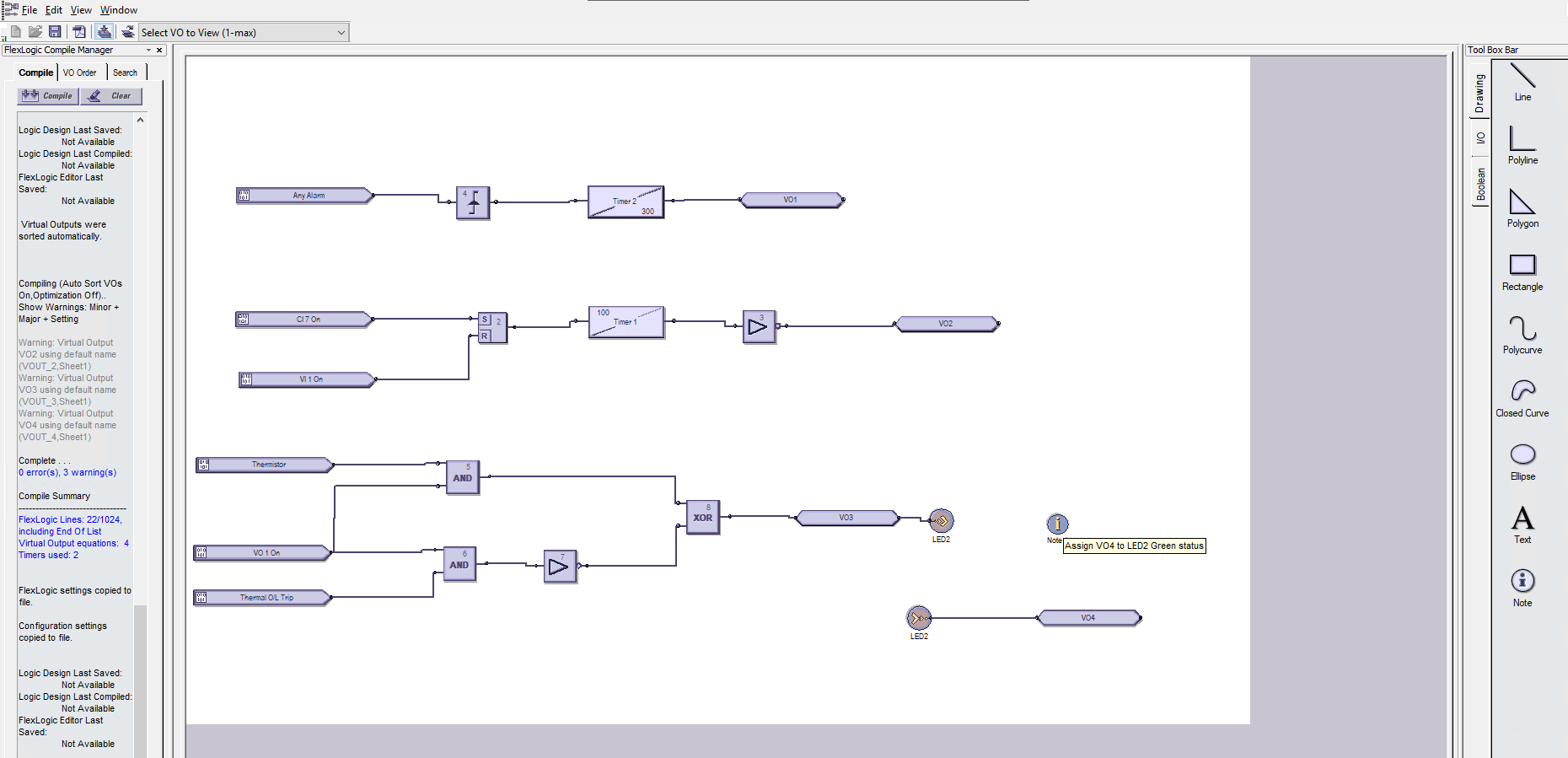 FlexLogic™ and additional I/O options allow the MM300 to replace local programmable controllers in LV applications.
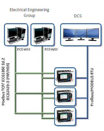 MM300 Enhanced Dual Architecture Communication
Communication
Key Features
- Networking Interfaces - Two Wire RS485, up to 2x RJ45 Ethernet
- Multiple Protocols (Modbus RTU, Modbus TCP, IEC61850 Ed.2, IEC62359-3 (PRP/HSR), internally powered Profibus)
- Programming Ports - USB, RS485, RJ45
- Network Time Protocol, IEEE1588 Precision Time Protocol
The MM300 Enhanced supports the most popular industry standard protocols enabling easy, direct integration into HMI and electrical SCADA systems. Modbus RTU and Modbus TCP is provided standard with a RS485 and RJ45 Ethernet networking port respectively.
The MM300 Enhanced can support concurrent operation of Serial, Fieldbus and Ethernet protocols. This enables MM300 Enhanced to communicate with DCS, Electrical Control System simultaneously and Integrate seamlessly with other protection & control devices on station bus. The Ethernet option in a device initially connected with a serial protocol can provision for a future communications upgrade to Ethernet.
User interface
Software
EnerVista Flex Toolsuite
The EnerVista toolsuite provides all the tools to monitor the status of the protected asset, maintain the relay, and integrate information measured by the MM300 Enhanced into DCS or SCADA monitoring systems. Convenient COMTRADE and Sequence of Events viewers are an integral part included with every MM300 Enhanced to carry out postmortem event analysis to ensure proper protection system operation.
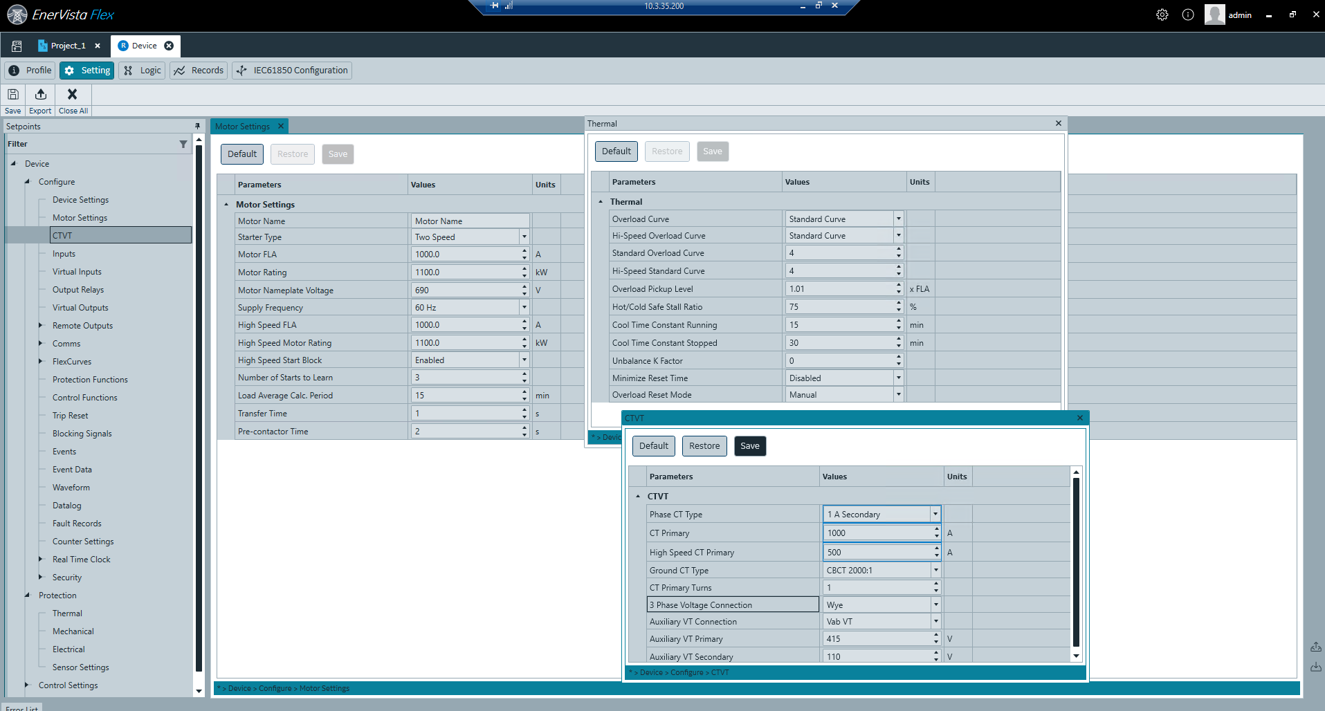 Configure MM300 Enhanced using intuitive EnervistaFlex setup program.
Cybersecurity
The MM300 Enhanced delivers a host of cybersecurity features that help operators to comply with NIS and NERC CIP guidelines, or other security regulations.
- Authentication/authorization/accounting server support (AAA - Radius)
- Role Based Access Control (RBAC)
- Non-erasable cyber event recorder (Syslog for SEM)
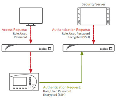 Cybersecurity with Radius Authentication
Protection and Control
The MM300 is a digital motor protection and control system, designed for Low Voltage motor applications. Flexible and powerful, the MM300’s protection can be scaled to the specific requirements of your system. Manufacturing for the MM300 has been Discontinued. Please contact GE Vernova for availability. As an alternative, please refer to MM300 Enhanced.
Key Features
- Enhanced Thermal Modeling
- Mechanical Jam / Stalled Rotor
- Undercurrent
- Underpower
- Acceleration Time
- Current Unbalance
- Ground Fault
- Sensitive Ground Fault
- Phase Overvoltage / Undervoltage
- Auxiliary Undervoltage
- Phase Reversal
- VT Fuse Failure
- Thermistor RTD
- Overtemperature
| DEVICE NUMBER | FUNCTION |
|---|---|
| 27AUX | Undervoltage - Auxiliary Input |
| 27 | Undervoltage - Three Phase |
| 37 | Undercurrent/Underpower |
| 38 | Bearing Temperature RTD |
| 46 | Current Unbalance |
| 47 | Voltage Phase Reversal |
| 49 | Thermal Overload |
| 50G | Ground Instantaneous Overcurrent |
| 50N | Neutral Instantenous Overcurrent |
| 51R | Locked/Stalled Rotor/Mechanical Jam |
| 59 | Overvoltage - Three Phase |
| 66 | Starts/Hour & Time Between Starts |
Monitoring & Metering
The MM300 includes high accuracy metering for all AC signals. Voltage, current, power metering, and temperature all available options. Current and voltage parameters are available as total RMS magnitude and angle.
Key Features
- Metering - current, voltage, power, energy, frequency, RTD, Thermistor
- Oscillography – analog values at 32 samples/cycle and digital states
- Event Recorder - Up to 256 time tagged events with 1ms res
- Advanced device health diagnostics
 Log motor operating parameters to allow for analyzing motor loading and performance over prolonged periods of time.
Advanced Automation
The MM300’s powerful I/O and programmable FlexLogic options offer advanced automation control, reducing the need for additional programmable controllers or discrete control relays.
 FlexLogic™ and additional I/O options allow the MM300 to replace local programmable controllers in LV applications, like conveyor belts as in this example
Advanced Communications
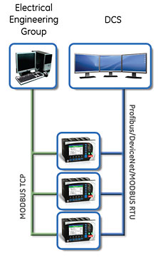
The MM300 utilizes the most advanced communications technologies available today making it the easiest and most flexible motor protection relay to use and integrate into new and existing infrastructures. Multiple communication ports and protocols allow control and easy access to information from the MM300. All communication ports are capable of communication simultaneously.
The MM300 supports the most popular industry standard protocols enabling easy, direct integration into HMI and electrical SCADA systems. Modbus RTU is provided standard with a RS485 networking port. The following optional protocols and communication ports are available:
Key Features
- Fieldbus Protocol with dedicated port
- ODVA Compliant DeviceNet
- Internally powered Profibus
- Modbus TCP/IP with RJ45 10/100baseT Ethernet port
User Interface
EnerVista™
The EnerVista™ Suite is an industry-leading set of software programs that simplifies every aspect of using the MM300. The EnerVista™ suite provides all the tools to monitor the status of the protected asset, maintain the relay, and integrate information measured by the MM300 into DCS or SCADA monitoring systems. Convenient COMTRADE and Sequence of Events viewers are an integral part of the EnerVista Setup software included with every MM300, to carry out postmortem event analysis to ensure proper protection system operation.
Recommended Products & services
Multilin Agile Motor Protection
GE Vernova’s Multilin Agile Motor Protection, with its compact footprint and advanced...
View More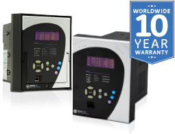
Multilin 339
The Multilin™ 339 is a member of the Multilin 3 Series protective relay platform and...
View More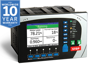
MM300
The MM300 integrates protection, control, automation, metering, diagnostics and multiple...
View MoreMultilin 339
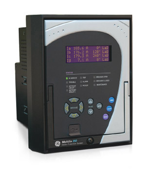
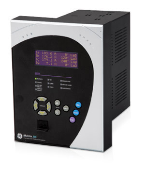
Motor protection systems
The Multilin™ 339 is a member of the Multilin 3 Series protective relay platform and has been designed for the protection, control and management of medium voltage motors in industrial applications. The Multilin 339 delivers unparalleled protection, control, diagnostics and communications in an industry leading drawout construction.
Multilin 339
Motor protection systems
The Multilin™ 339 is a member of the Multilin 3 Series protective relay platform and has been designed for the protection, control and management of medium voltage motors in industrial applications. The Multilin 339 delivers unparalleled protection, control, diagnostics and communications in an industry leading drawout construction.
Key Features
- Thermal model biased with RTD and negative sequence current feedback
- Under Voltage
- Over Voltage
- Under/Over Frequency
- Phase and ground TOC and IOC
- Start supervision and inhibit
- Mechanical Jam
- Current Phase Reversal
- Acceleration Time
- Undercurrent / Underpower
- Starts per Hour
Protection & Control
The 339 motor protection system is designed to protect and manage various sizes of LV and MV asynchronous motors motors and driven equipment. Flexible and powerful, the 339 provides advanced motor protection, control and monitoring in one integrated, economical drawout or non-drawout design. The 339 contains a full range of self contained protection and control elements as detailed in the Functional Block Diagram and Features table.
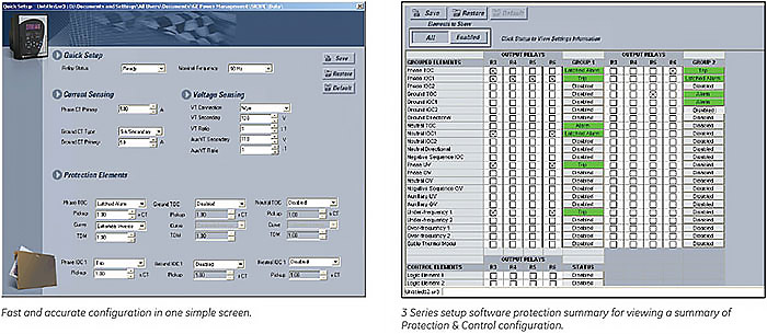
Block Diagram and Features table.
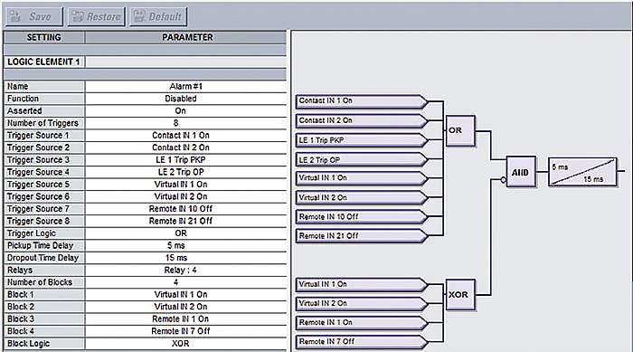 Sixteen logic elements available for applications such as manual control, interlocking and peer to peer tripping.
Key Features
- Comprehensive metering
- Programmable oscillography up to 32 samples per cycle and digital states
- SNTP or IRIG-B clock synchronization
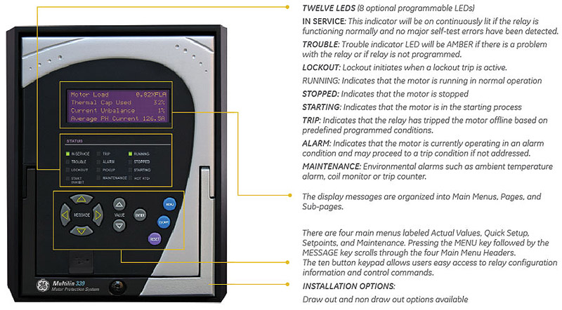
- 4X20 character LCD display
- Control panel with 12 LED indicators
- Motor health and switchgear diagnostics including breaker monitoring, CT/VT and close/trip coil supervision
- Relay health diagnostics
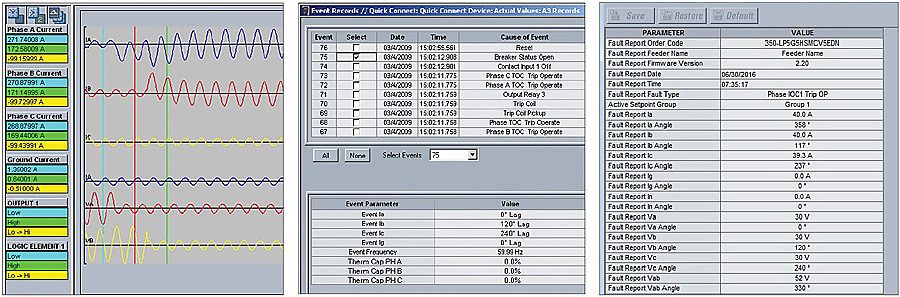
Power System Troubleshooting
Analyze power system disturbances with transient fault recorder and event records
Metering, Monitoring & Diagnostics
Time Synchronization and IRIG-B:
An IRIG-B input is provided in the 339 to allow time synchronization using a GPS clock over a wide area. The 339 IRIG-B supports both AM and DC time synchronization, with an auto detect feature that that eliminates the need for configuration.
Temperature Monitoring:
The 339 continually monitors ambient temperature around the relay and alarms when device is exposed to extreme temperatures.
Advanced Device Health Diagnostic:
The 339 performs comprehensive device health diagnostic tests during startup and continuously at runtime to test major functions and critical hardware. These diagnostic tests monitor for conditions that could impact system reliability.
 The Motor Heath Report allows you to easily “see” how your motor is doing:
- Start/stop history
- Comprehensive trip details
- Learned acceleration time and starting current
- Many other motor health details
Key Features
- Front USB and rear serial, Ethernet and Fiber ports
- Multiple Protocols: IEC 61850, MODBUS TCP/IP, MODBUS RTU, DNP 3.0,IEC60870-5-104, IEC60870-5-103
Advanced Communications
The 339 utilizes the most advanced communication technologies today making it the easiest and most flexible motor protection relay to use and integrate into new and existing infrastructures. Multiple communication ports and protocols allow control and easy access to information from the 339. All communication ports are capable of communicating simultaneously. With our advanced draw-out construction, the 339 relay can be drawn-out without having to disconnect any communication cables.
The 339 supports the most popular industry standard protocols enabling easy, direct integration into electrical SCADA and HMI systems. Modbus RTU is provided as standard with a RS485 networking port. The following optional protocols are available:
- IEC 61850 GOOSE
- DNP 3.0
- Modbus RTU
- Modbus TCP/IP
- IEC 60870-5-103
- IEC 60870-5-104
These protocols make it easy to connect to a Utility or Industrial automation system, eliminating the need for external protocol converter devices.
EnerVista Software
The EnerVista suite is an industry leading set of software programs that simplifies every aspect of using the 339 relay. The EnerVista suite provides all the tools to monitor the status of the protected asset, maintain the relay, and integrate the information measured into DCS or SCADA monitoring systems. Convenient COMTRADE and sequence of event viewers are an integral part of the 339 set up software and are included to ensure proper protection and system.
Learn More![]()
Feeder protection settings in one easy step
Access Control
Multilin devices and relays are designed with simple but powerful security to enable reliability and compliance for virtually any project or implementation. Password security is an optional feature of the 3 Series which can be setup using the SR3 EnerVista Setup software. The password system has been designed to facilitate a hierarchy for centralized management. This is accomplished through a Master level access password which can be used for resetting lower level access passwords and higher level privileged operations.
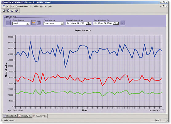
Auditing and Reporting
With the Security Audit Trail reporting feature, available in GE Vernova’s ViewPoint Monitoring software, operators are able to obtain Event logging reports of key activities such as configuration changes. These pre-formatted reports can be used to help ensure device and protection system integrity and perform forensic auditing of activities and changes for compliance.
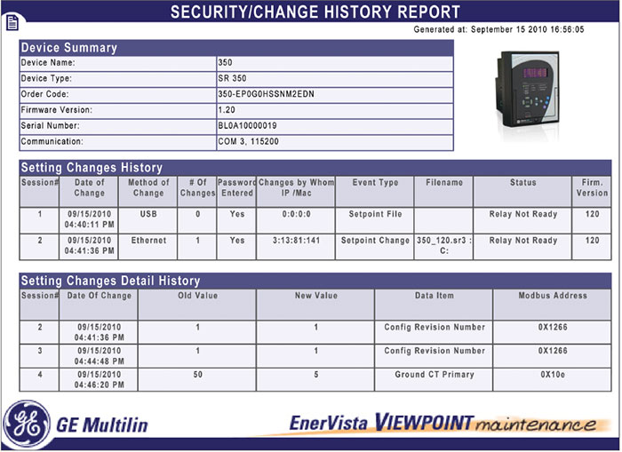 Trace any setting changes with security audit trail
Hardware
Inputs and Outputs
The 339 features the following inputs and outputs for monitoring and control of typical motor applications:
- 10 contact Inputs with programmable thresholds
- 7 Outputs (2 Form A, 5 Form C) as standard and 4 Outputs (1 Form A, 3 Form C) when internal RTD option is selected
- 5 Form C output relays
Drawout & Non-Drawout Construction
The 339 is offered in both a drawout or a non-drawout construction. In the drawout case design the 339 simplifies installation and improves site safety as the need to open switchgear doors or rewire the device after testing is eliminated.
The 339 protection relay chassis used with a draw out relay is available separately, for use as a partial replacement or in test environments. The draw out relay with no chassis is also available to order as a spare unit.
Application Flexibility & Ease of Wiring
Removable terminals ease wiring and in-system testing or troubleshooting.
Optional RTD
Reduce wiring via remote RTD’s using the RMIO module and support for 3 internal RTD
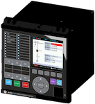
 Drawout
 Non-drawout
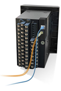
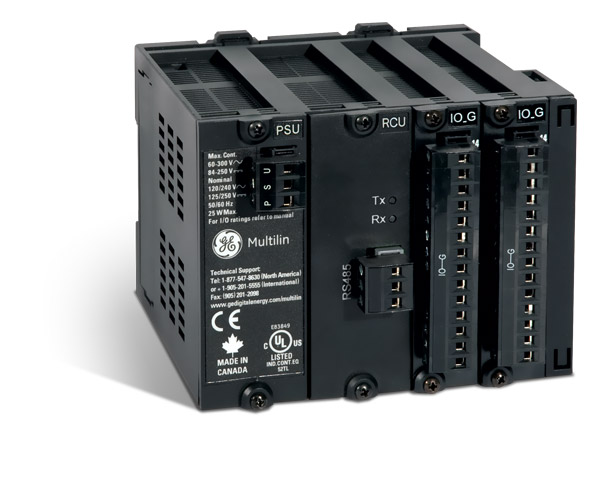 Remote RTD Module
User Interface
Retrofit Existing Multilin MII Family Devices
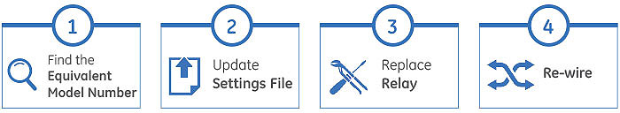
Traditionally, retrofitting or upgrading an existing relay has been a challenging and time consuming task often requiring re-engineering, panel modifications and re-wiring. Similar features and form factor of some models of MII family devices allow users to replace their existing relays with 3 Series relays with enhanced protection and control features and advanced communications.
The SR3 EnerVista Setup software allows users to create new setting files based on existing MIFII and MIVII setting files and can be uploaded to a 350 relay with a compatible model number. Retrofit is smooth and simplified with minor wiring or switchgear modifications.
Recommended Products & services
Multilin Agile Motor Protection
GE Vernova’s Multilin Agile Motor Protection, with its compact footprint and advanced...
View More
Multilin 339
The Multilin™ 339 is a member of the Multilin 3 Series protective relay platform and...
View More
MM300
The MM300 integrates protection, control, automation, metering, diagnostics and multiple...
View More