DS Agile Digital Control System
DS Agile, GE Vernova’s Digital Control System, includes customer-inspired evolutions and combines advanced hardware, cutting-edge software and communications capabilities to provide advanced and secured protection, control and automation solutions in digital substations. DS Agile provides features such as integrated condition monitoring for online substation situational awareness, IEC 61850 Ed 2, Parallel Redundant Protocol (PRP) and High Availability Seamless Redundancy (HSR) architecture and full integration with control room network management and smart grid applications.
Recommended Products & services
Substation Systems
Electric utilities and independent power producers are under increasing pressure to...
View More
Integrated Substation Control System
Next generation substation control and automation Network operators/owners are seeing...
View More
DS Agile Substation Gateway
GE Vernova’s DS Agile Substation Gateway substation gateways perform the...
View MoreDS Agile Substation Gateway
GE Vernova’s DS Agile Substation Gateway substation gateways perform the communication interface between the electrical substation and the area dispatch centers (SCADA), allowing SCADA operators to remotely control and monitor the substation in coherence with the operation of the whole area of the electrical grid.
DS Agile Substation Gateway
GE Vernova’s DS Agile Substation Gateway substation gateways perform the communication interface between the electrical substation and the area dispatch centers (SCADA), allowing SCADA operators to remotely control and monitor the substation in coherence with the operation of the whole area of the electrical grid.
Recommended Products & services
Substation Systems
Electric utilities and independent power producers are under increasing pressure to...
View More
Integrated Substation Control System
Next generation substation control and automation Network operators/owners are seeing...
View More
DS Agile Substation Gateway
GE Vernova’s DS Agile Substation Gateway substation gateways perform the...
View MoreGridcom T390
Universal Power Line Carrier (PLC) for High Voltage (HV) Transmission Lines
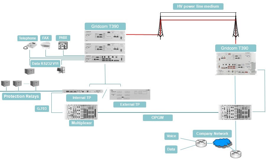
GE Vernova’s Gridcom T390 is an integrated system, combining high performance and flexibility, which allows utilities to reliably transmit voice, data, teleprotection and other services over HV transmission lines.
Gridcom T390
Universal Power Line Carrier (PLC) for High Voltage (HV) Transmission Lines
GE Vernova’s Gridcom T390 is an integrated system, combining high performance and flexibility, which allows utilities to reliably transmit voice, data, teleprotection and other services over HV transmission lines.
Improved Capacity & Efficiency
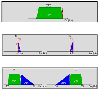
Offering superimposed mode and teleprotection over QAM for the highest LAN to LAN performance for your applications
High speed transmission for RTU: Some RTU's may require higher communication capabilities for SCADA. Some substations have to provide communication capabilities to perform remote operations such as configuration, telemaintenence, and monitoring. Since these services are mainly over IP, they require up to several hundred kbits/s for transmission.
Equipped with an Ethernet interface, Gridcom T390 can transmit LAN and WAN information from one end to the other. This feature, designed to support IP traffic transmission on energy company networks, implements an L2 bridge at network level (full transparent bridging) with advanced capabilities, compliant with 802.1q for VLAN transport, capable to go upto 320kbits/s @ 48 kHz total bandwidth in superimposed mode.
Gridcom T390 superimposed mode is desigend to allow transmission (TX) and reception (RX) to share the same frequency band. Superimposed mode is vital for digital PLC applications as it allows optimal bandwidth optimization, and can reduce the total bandwidth occupation by half.
Secure & Reliable Solution
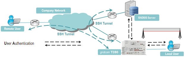
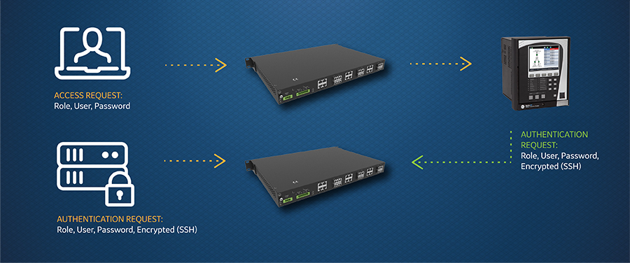
The Gridcom T390's RADIUS Remote User Authentication and SSH encryption adapts to your centralized user management topology with guaranteed communication confidentiality and data integrity between the PLC and the user.
- Remote user access is secured by UserAuthentication (via RADIUS or PLC).
- Local user can securely access PLC by submitting login/password per connection.
- Communication between remote user and the Gridcom T390 is secured by SSH tunnel encryption (Algorithm AES128, 3DES).
- Radius failure management is realized with RADIUS authentication mode fallback to PLC authentication mode.
 Enhanced Security Features for Remote Users
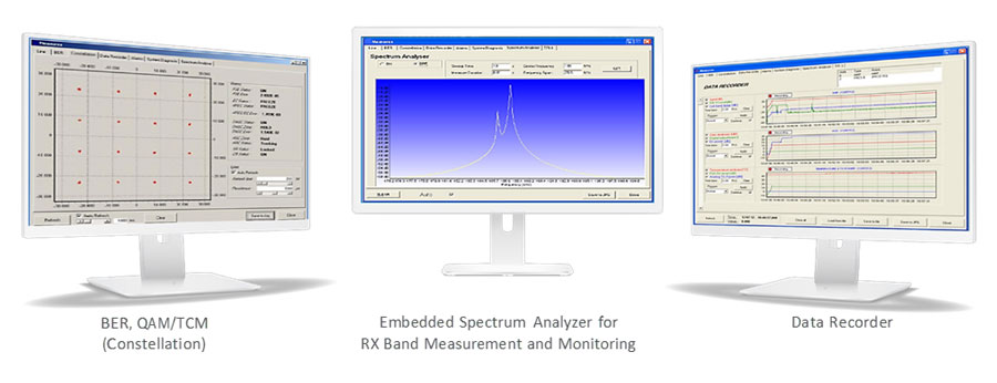
High Level of Configuration & Customization
Offering a powerful, embedded HMI configuration, commissioning, and test tool.
| The Windows based HMI provides a comprehensive set of features including: | Numerous operations are available in maintenance (TEST) mode: |
|---|---|
|
|
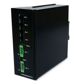
 Front panel mounting
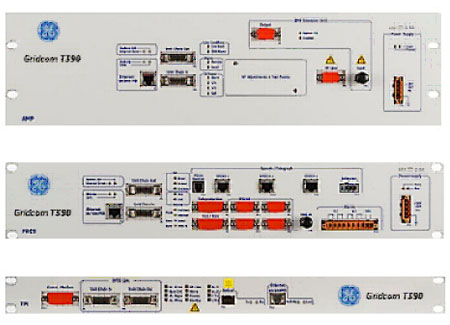
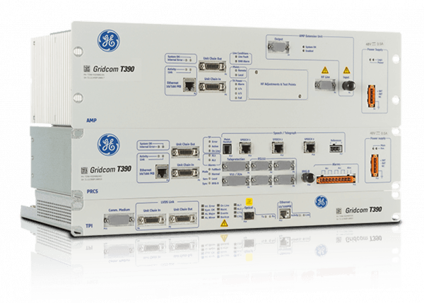
Integrated & Modular with Front Panel Mounting
Gridcom T390 integrates:
- Amplifier unit: AMP/AMPX offers adjustable (2-80W) transmission power
- Processing unit: PRCS
- Optional, integrated Teleprotection unit: TPI provides up to 4 independent commands, with 8 input contacts and 14 heavy duty outputs
Each unit can be installed separately for a specific function, and can be configured to customer requirements, offering a high level of flexibility without any factory returns. All connections, including the power supply, are on the front of the unit for easy access for maintenance and checks.
 Transmission Mode
Versatile System, Supporting Analog, Digital & Mix Mode
Offering perfect operational flexibility, GE Vernova’s Gridcom T390 supports Analog, Digital, and mixed transmission on the same hardware platform. Customers can purchase an analog PLC, then upgrade with a simple firmware key activation, if the condition and application allow it. Compared to a conventional chassis, the number of interfaces is not restricted by the size of the chassis.
 Typical Applications
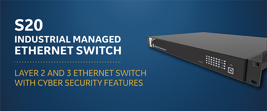
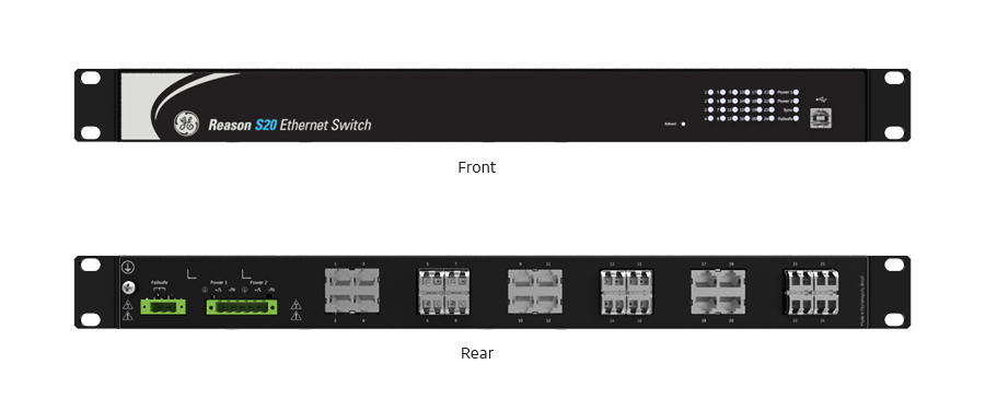
Reason S20
Managed Ethernet Switches
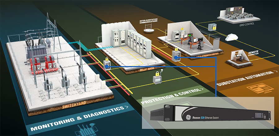
GE Vernova’s Reason S20 series of managed Ethernet switches are designed to enable an IEC 61850 digital substation network, including IEEE 1588v2 (PTP), in harsh environments within power systems and industry applications. Using the Reason S20, packet switching between substation devices is flexible, reliable and robust, even in situations where routing is necessary.
A flexible, modular design allows the Reason S20 series to support a wide range of network architectures. The Reason S20 series includes the following models:
Reason S20
Managed Ethernet Switches
GE Vernova’s Reason S20 series of managed Ethernet switches are designed to enable an IEC 61850 digital substation network, including IEEE 1588v2 (PTP), in harsh environments within power systems and industry applications. Using the Reason S20, packet switching between substation devices is flexible, reliable and robust, even in situations where routing is necessary.
A flexible, modular design allows the Reason S20 series to support a wide range of network architectures. The Reason S20 series includes the following models:
The firmware 07A07 versions adds Digital Diagnostics Monitoring (DDM) functionality for optical SFP transceivers as well as new alarms using the dry-contact relay or SNMP traps were add based on DDM measurements. For the full list of enhancements, please refer to the firmware release notes.
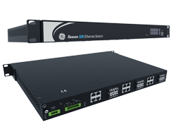
S20 Hardware version C
GE Vernova’s Reason S20 design has been enhanced with hardware version C, delivering a brand-new High Voltage power supply and other updates, enabling:
- Full compliance with environment and EMC requirements of IEC 61850-3 edition 2
- Full compliance with environment and EMC requirements of IEEE 1613:2009 and its extension IEEE 1613.1:2013.
- UL 60950-1 recognition
- Real Time Clock (RTC) along with a supercapacitor activity for 2 days after S20 is powered-off.
Reason S20 integrates with MDS PulseNET (FW 07A03)
MDS PulseNET (v4.5.0) network management software has been modified to include configuration management and backups, syslog servers and numerous other features specific to GE Vernova Reason products. Switches can now be discovered and managed quickly and easily as part of the overall Industrial Communications eco-system.
Main NMS features:
- System monitoring (alarms, ports, health status)
- Centralized Configuration Management (including backup)
- Automatic system discovery based on a range of IP addresses
Layer 3 functionalities (FW 07A)
S20 supports Layer 3 capabilities, featuring the following protocols:
- Routing Information Protocol (RIP) version 1 and 2 - RFC 1058 and RFC 2453
- Open Shortest Path First (OSPF) version 2 - RFC 2328
- Virtual Router Redundancy Protocol (VRRP) - RFC 2338
- Static Routing
Key Benefits
The flexible and robust Reason S20 Ethernet switches provide customers with a variety of benefits, including:
- Network Management Software (NMS) integration with MDS PulseNET (v4.5.0)
- Layer 2 and 3 Managed Ethernet Switch
- Fully flexible Ethernet switch for industrial applications, including PRP redundant networks
- Ready for IEC 61850 networks (tests performed by KEMA)
- Store-and-forward packet switching
- Media Access Control (MAC) bridges and Spanning Tree Protocol as standardized by the IEEE 802.1D
- IP Routing functionalities: Static, Routing Information Protocol (RIP) and Open Shortest Path First (OSPF)
- Virtual Router Redundancy Protocol (VRRP) to eliminate a single point of failure in static routed environments
- UltraRSTP (Rapid Spanning Tree Protocol - IEEE 802.1W) with fault recovery time less than 5 ms per hop, meeting IEC 61850-90-4 specifications
- Bridge Protocol Data Unit (BPDU) guard and filtering to prevent external interference in Spanning Tree networks
- Cyber Security enhancements, been ready for NERC CIP requirements
- Support for IPv4 and IPv6 protocols (Multicast, Unicast and Broadcast operation)
- Internal clock synchronization using NTP protocol
- Operation as NTP server using IEEE 1588v2 as source of time
- Alarm contacts for detection of critical events
- Standard USB 2.0 configuration port
Cybersecurity
 The Reason S20 delivers advanced cyber security features
The Reason S20 delivers advanced cyber security features that help operators to comply with NERC CIP guidelines and regulations. These features are standard with firmware 06A02 and greater.
AAA Server Support (Radius/TACACS+)
Enables integration with centrally managed authentication and accounting of all user activities and uses modern industry best practices and standards that meet and exceed NERC CIP requirements for authentication and password management.
Role Based Access Control (RBAC)
Efficiently administrate users and their privileges within S20 devices. Multiple users account with independent passwords and privilege levels (roles) may be created, and with an advanced function leveling it is possible to define the access level required for each predefined function. Attempts to log-in (either successful or failed) are stored in a persistent flash memory syslog. After three failed log-in attempts, the user account gets locked out and must wait 1 minute to retry new three attempts.
Password Complexity, Encryption and Expiration
Factory default password is different for each manufactured device and after the first login, users must change the password with at least 8 characters including lower/uppercase alphabetic, numeric and special non alphabetic characters (e.g. #, $, @, &). Passwords are encrypted using SHA256 and by default, it may expire after 6 months (user-configurable).
Firmware digitally signed and secure communications
To perform a secure firmware update, S20 uses the checksum algorithm to check firmware integrity and a digital signature to ensure its authenticity. In addition, only the encrypted Secure File Transfer Protocol (SFTP) is enabled to transfer the firmware file. By default, only secure protocols such as SSH (CLI) and HTTPS (graphic web interface) are activated to establish remote access to S20, and if desired they may be deactivated as well as unused Ethernet ports, leaving only the local USB Serial communication through SSH available.
Design
The flexible design of Reason S20 allows the user to customize each group of 4 ports interfaces to either electrical (RJ45 fixed/SFP) or optical (SFP), Fast Ethernet or Gigabit. In addition, S20 may have a redundant power supply which does not need to be identical to the main one. The power supply options are the full range high voltage 125-250 VDC / 110-240 VAC (50/60 Hz) or the low voltage 24/48 VDC.
Field proven design backed by extensive type testing to ensure the robustness of the S20’s fanless design for harsh substation environments. The EMC and Environmental tests are in accordance with IEC 60255-26, IEC 61850-3 Ed. 2, IEEE 1613 and its extension IEEE 1613.1. Safety requirements are in accordance with IEC 60255-27 and UL 60950-1.
IEC 61850 Networks
The Reason S20 is compliant with IEC 61850 for applications in substations, proven by an extensive type testing to demonstrate the EMC and environment robustness and a functional and performance test report issued by KEMA. The test scope included . The test scope included VLAN function, QoS function for GOOSE messages, network recovery performance (RSTP) and booting time. The Reason S20 UltraRSTP achieves a fault recovery time of less than 5ms per hop, reducing packets loss while maintaining interoperability with others standard RSTP devices. For zero recovery time, S20 is ready for PRP networks schemes.
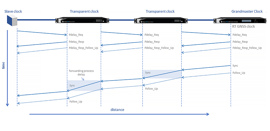
 Reason S20 operates either as a transparent clock or boundary clock to ensure time accuracy for PTP-aware IEDs in the network
IEEE 1588v2
Precision Time Protocol (PTP) is defined in the IEEE 1588 standard, which describes the precision clock synchronization protocol for networked measurement and control systems. Reason S20 complies with IEEE1588v2, and can operate either as transparent clock or boundary clock to ensure time accuracy for PTP-aware IEDs in the network. All S20 interface ports may operate as PTP-aware, achieving the nanosecond accuracy given the hardware based implementation.
 Reason S20 operates either as a transparent clock or boundary clock to ensure time accuracy for PTP-aware IEDs in the network
SFP Transceivers
If you have free SFP slots, or require replacing SFP transceivers, GE Vernova offers the following:
| Code | Description |
| SFP1GFO20K | SFP Transceiver 1000Mbps LC single mode, 1310nm wavelength, 20km |
| SFP1GFO40K | SFP Transceiver 1000Mbps LC single mode, 1310nm wavelength, 40km |
| SFP1GFO80K | SFP Transceiver 1000Mbps LC single mode, 1550nm wavelength, 80km |
| SFP1GFO05K | SFP Transceiver 1000Mbps LC multi mode, 850nm wavelength, 500m |
| SFP01GFO2K | SFP Transceiver 100Mbps LC multi mode, 1310nm wavelength, 2km |
| SFP1GCU02K | SFP Transceiver 10/100/1000Mbps, RJ45 connector |
| The following models have been discontinued as of November 2023. View last-time buy announcements. | |
| SFP1GFO120K | SFP Transceiver 1000Mbps LC single mode, 1550nm wavelength, 120km |
| SFP01GFO20K | SFP Transceiver 100 Mbps LC single mode, 1310 nm wavelength, 20 km |
Recommended Products & services
Reason S20
GE Vernova’s Reason S20 series of managed Ethernet switches are designed to enable...
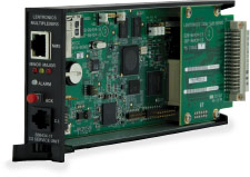
View MoreLentronics E1MXe
Multiplexer
Multiplexing Solutions for Critical Communications
The Lentronics™ E1MXe Multiplexer is a powerful, flexible and reliable solution for converged service networks. The E1MXe extends critical channel access into harsh utility environments over microwave radio, leased line and dedicated fiber optic or copper cable networks.
Lentronics E1MXe
Multiplexer
Multiplexing Solutions for Critical Communications
The Lentronics™ E1MXe Multiplexer is a powerful, flexible and reliable solution for converged service networks. The E1MXe extends critical channel access into harsh utility environments over microwave radio, leased line and dedicated fiber optic or copper cable networks.
Recommended Products & services
Cyber Secured Service Unit
GE Vernova’s Lentronics™ Cyber Secured Service Unit (CSSU) protects Lentronics...
View More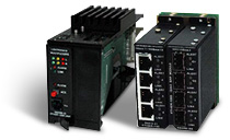
Ether-1000 Unit
Built for critical ethernet communications Unparalleled network security and performance...
View More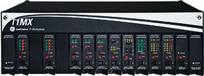
Lentronics T1 Multiplexer
Multiplexing Solutions for Critical Communications The Lentronics™ JungleMUX T1...
View MoreTTMX Teleprotection Terminal
Fast and Secure Teleprotection for Transmission and Distribution Grids
Protecting your critical assets after a fault is crucial to maintaining power system stability and safety. Existing technologies are becoming harder to implement with telephone companies suspending their connection leases.
What’s need is a standards-based communications solution that is simple to implement, provides fault protection in harsh operating conditions and provides the reliability needed to address teleprotection, including Direct Transfer Trip, Permissive Transfer Trip, blocking and unblocking applications.
TTMX Teleprotection Terminal
Fast and Secure Teleprotection for Transmission and Distribution Grids
Protecting your critical assets after a fault is crucial to maintaining power system stability and safety. Existing technologies are becoming harder to implement with telephone companies suspending their connection leases.
What’s need is a standards-based communications solution that is simple to implement, provides fault protection in harsh operating conditions and provides the reliability needed to address teleprotection, including Direct Transfer Trip, Permissive Transfer Trip, blocking and unblocking applications.
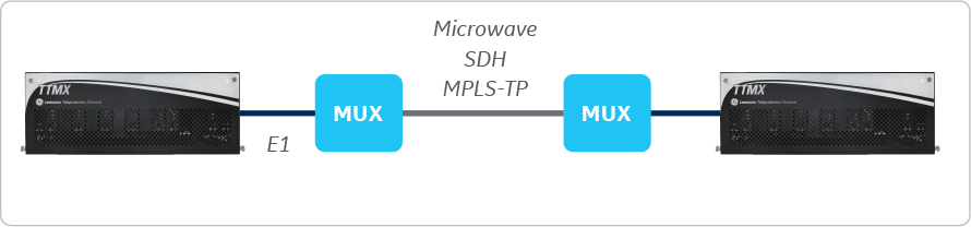
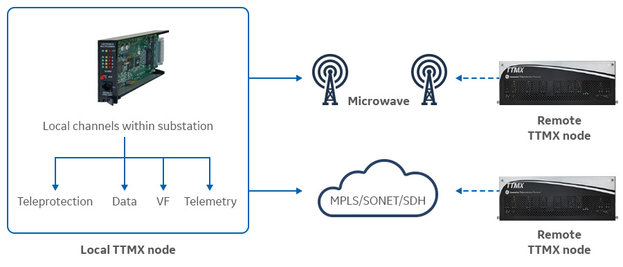
The TTMX platform offers 15 shelf slots with capability of adding optional expansion chassis. Compact digital access controllers offer four E1 interfaces to support fiber-optic or copper connections when connected to a higher-order transport system (microwave/SDH/MPLS).
TTMX offers a whole spectrum of modular options flexibly added to base platform. The solution is powered through 48/130 vDC station batteries with a bank of modular and hot-swappable interface units, available in the following options:
Base Teleprotection platform
- Chassis
- Power supply
- CDAX
- DTT-XMT/RCV
Channel Options
- 2/4 Wire VF
- FXO/FXS
- RS 232
- PTM Data
- G.703 Data
- NX64 Data (Optical & Electrical)
- Contact I/O
- Ethernet (64 – 768kb/s)
NMS & Security Options
- NMX module
- VistaNET element manager
- Advanced NMS
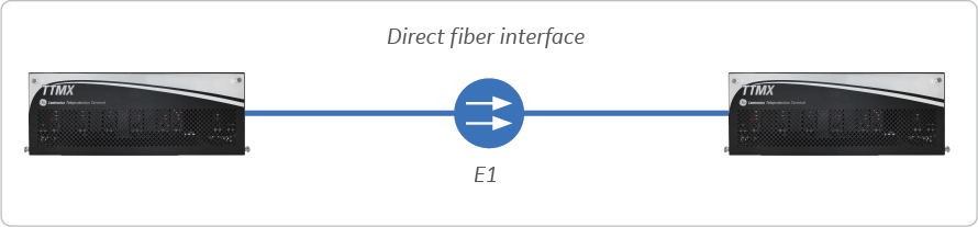
Typical Configurations
P2P Configuration – Direct Fiber Interface
Simplest configuration—point-to-point over a dedicated fiber connection.
P2P Configuration – Established Link
With a high capacity point-to-point established link, such as a Multiplexer or Microwave, you can connect the TTMX to standard interfaces.
P2P Configuration – Transport Media Redundancy
With two transport media options available, the TTMX can provide a redundant solution.

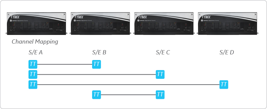
P2P Configuration – Multi-terminal
Add/Drop flexibility provides point-to-point connectivity between any two sites on the network.
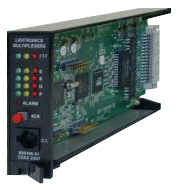
What is the CDAX ?
CDAX is the E1 interface card on the Lentronics Teleprotection platform, operating as a Compact Digital Access X-connect (CDAX)
Supports configurable drop-port modes
- Channelized E1
- Channel bus (CBUS)
Integrated 64 kbps level cross connect
- Grooms and consolidate 64 kb/s to/from multiple E1s or CBUS ports
- Hairpin 64 kb/s traffic between E1/64 kb/s signals
Direct Transfer Trip (DTT) Unit B86441-42 DTT-Tx/Rx UNIT
Transmit Functions
- 2 Transmit commands
- End-to-End trip time <3ms
- Dual keying loops for improved dependability
- Continuous integrity monitoring
- Spurious trip immunity (software)
- Transmit Minimum Trip Time and Trip Extension Time (software adjustable)
- “Active Tripping” contacts for local monitoring (SER)
- BC-96 Code format for high dependability and security
- Form C alarm relay
- Keying loops operate 48, 130, 250 VDC station battery
- Adjustable spurious trip immunity, 1ms increment to 20ms
- Two firmware images, active and standby
Receive Functions
- 2 Receive commands
- Main trip output
- Dual series drivers for trip output security
- Continuous integrity monitoring
- 1A, 150 VDC output relays (continuous)
- Aux trip output @ same rating
- Receive Minimum Trip Time and Trip Extension Time (software adjustable)
- Immune to single component failures (no false trip)
- Form-C alarm relay for unit and per loop Form-C relay for port monitoring
- Dielectrically isolated outputs for SWC immunity
- RFI immunity

DTT signals connected to the relay can be tested by a dedicated test panel (B86429) which allows complete end-to-end testing without disconnecting the protection relays.

B86466 DATA-G703 Unit
- Synchronous data transmission at 64 kb/s
- G.703 Interface with codirectional timing
- Visual indication of data port activity
- Provides “Yellow” alarm to help troubleshooting
- Circuit addressing
- Supports local loopback, line loopback, local and line loopback
- Built-in PRBS generator and analyzer
- Form-C alarm relay
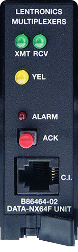
B86464 DATA-NX64F Unit
- Provides an interface for interference-free intra-substation data link between TTMX node and Relay (high RFI immunity)
- Complies to IEEE C37.94 Standard
- Operates with up to 2 km long multimode duplex fiber (50µm or 62.5µm) using ST connector
- Provides “Yellow” alarm to help troubleshooting
- Alerts for loss of either fiber
- Supports 64 kb/s, 128 kb/s,… 768 kb/s data transmission (software configurable)
- Visual indication of data port activity
- Circuit Addressing
- Supports local, line and local+line loopbacks
- Built-in PRBS generator and analyzer
- End-to-End compatible with 86464-01 unit (V.35)
B86464 DATA - NX64 Unit
- Synchronous data transmission at rates from 64 kb/s to 768 kb/s in increments of 64 kb/s
- V.35 Interface or 10/100Mbps Ethernet
- Visual indication of data port activity
- Supports clock polarity inversion
- Software configurable as DCE or DTE
- Internal or External transmit clock timing
- Circuit Addressing
- Supports local loopback, line loopback, local+line loopback
- Built-in PRBS generator and analyzer
- IN and OUT control lines (all local)
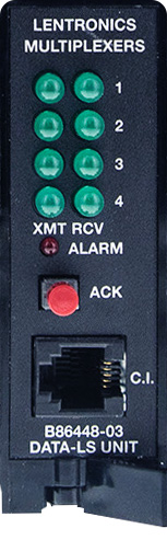
86448 DATA-LS Unit
- Supports point-to-point RS-232 asynchronous data circuits
- Configured for one, two or four active data ports per card
- Maximum baud rates of 38.4 kb/s, 19.2 kb/s or 9.6 kb/s
- All data ports accept sub-multiple rates of the configured Maximum Baud Rate (MBR / 2n, n=0,1,2…)
- Visual indication of data port activity
- Supports local loopback, line loopback, local + line loopback
- Four Control Lines accompany data ports
- Built-in PRBS generator and analyzer for testing individual data circuits
B86445-32 2W VF FXS UNIT (2-Channel)
- Software adjustable VF levels in 0.1 dB steps
- -9.5 dBm to +5.0 dBm (Transmit)
- -15.0 dBm to +5.0 dBm (Receive)
- Supports Loop Start, Ground Start and PLAR signalling applications
- Selectable Line Impedance and Network Build-Out Capacitance (software only)
- Bantam jack allows access to VF signal
- Programmable for “Splitting” or “Bridging”
- Loopback commands for VF testing
- On-board ringing generator & Talk Battery
B86445-42 2W VF FXO UNIT (4-Channel)
- Software adjustable VF levels in 0.1 dB steps
- -10.0 dBm to +3.0 dBm (Transmit)
- -12.0 dBm to +2.0 dBm (Receive)
- Supports Loop Start and Ground Start signaling
- Selectable Line Impedance (software only)
- Bantam jack allows bridging access to any of the four VF signals
- NOTE: VF tests require presence of loop current
- Loopback commands for VF testing

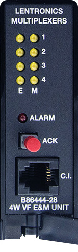
B86444 -08/-28 4W VF UNIT (1 or 4-Channel)
- 4WVF circuits, with Type I-V E&M
- Transmit and Receive levels software adjustable in 0.1 dB steps
- -17.5 dBm to +6.5 dBm (Transmit)
- -11.0 dBm to +10.0 dBm (Receive)
- Custom signal pattern
- Test features:
- Local and Line Loopbacks
- Synthesized 1 kHz tone can be sent to far or near end for test purposes
- Forced off-hook state on E-lead at near or far end
- Two firmware images, active and standby
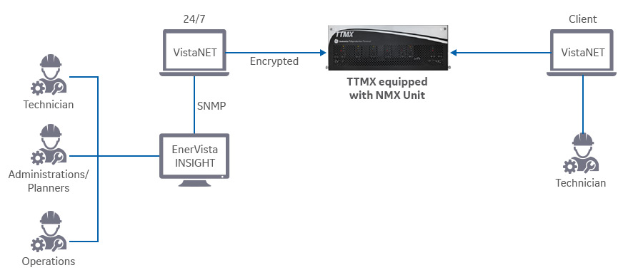
VistaNET™ EMS for GE Vernova Multiplexers
- A Windows PC/Server-based NMS that provides 24/7 monitoring, configuration and administration of your Teleprotection Terminal Multiplexers (TTMX)
- Interfaces to GE Vernova’s advanced NMS solution via SNMPv1, 2c and 3 offering security and confidentiality
- Connectivity to the TTMX network can be serial or Ethernet
NMX Unit
NMX units enables Ethernet-based connectivity for Network Management traffic between VistaNET and the TTMX hardware. The NMX unit can be optionally additionally secured through a TLS-based encryption module.
Ethernet connectivity for NMS
Redundancy
Optional redundant NMX unit at an alternate location is possible. VistaNET monitors and controls the network through both the nodes and chooses primary / back-up dynamically.
Specifications
| E1 Interfaces | |
|---|---|
| Line Rate | 2.048 Mb/s ± 50 ppm |
| Line Code Options | HDB3 and AMI |
| Framing Format | CRC multi-frame |
| Signaling multi-frame (CAS) | |
| Per ITU-T G.704 | |
| PRBS Generator | 211-1, 215-1 |
| Pulse Shape | ITU-T G.703 compliant |
| Nominal Line Impedance | 120 Ω balanced ± 5% resistive |
| Connectors | RJ-48C for electrical E1 (balanced) |
| SFP cages for optical E1 | |
| 3-pin header for both major and minor shelf alarm contact outputs | |
| 3-pin header for shelf power supply(s) alarm contact input | |
| Teleprotection Interfaces | |
|---|---|
| Transfer Trip | Separate transmit and receive units |
| Nx64 kb/s Data Optical | N=1 to 12 64kb/s channels |
| IEEE C.37.94 standard for fiber optical connection to protection relays | |
| G.703 Data | 64 kb/s channel supporting co-directional timing and Form-C relay alarm output |
| Environmental | |
|---|---|
| Operating Temperature | -20°C to +60°C (-4°F to +140°F) |
| Storage Temperature | -40°C to +70°C (-40°F to +158°F) |
| Humidity | 5-95% non-condensing |
| Earthquake | Earthquake Risk Zone-4 shock and vibration |
| Environmental – Electric Power Substation | |
|---|---|
| EMI/RFI | Designed to meet ANSI/IEEE C37.90.2 RFI |
| SWC/ISOLATION | Designed to meet ANSI/IEEE C37.90.1 SWC |
| Physical Data | |
|---|---|
| Height | 133 mm (5.25 inches) |
| Width | 483 mm (19 inches) |
| Depth | 413 mm (16.25 inches) |
| Weight | Dependent upon configuration |
| Optional Interfaces | |
|---|---|
| DATA INTERFACES | |
| Low Speed Data | RS232 interface |
| Sub-rate multiplexing | |
| Point-to-point and multi-point | |
| Synchronous and asynchronous | |
| High Speed Data | 64 (56) kb/s rates |
| RS422, V.35, G.703 and OCUDP interfaces | |
| Nx64 kb/s Data Electrical | N = 1 to 12 64 kb/s channels |
| TELEMETRY INTERFACES | |
| Contact Input/Output | Transport of contact closure |
| VOICE INTERFACES | |
| 4W VF | Optional E&M signaling |
| Point-to-point and multi-point | |
| 2W VF | Optional E&M signaling |
| 2W Foreign Exchange | Loop, ground or PLAR signaling |
| System Alarms | |
|---|---|
| Major | Form-C alarm relay (singular) |
| Minor | Form-C alarm relay (singular) |
| Power |
|---|
| 48 VDC or 130 VDC |
| Optional redundant power supply units |
| Certifications |
|---|
| IEC 60834-1 Teleprotection Performance |
| Network Management |
|---|
| VistaNET, operating on MS-Windows based PCs, allows network access via E1 or SDH Multiplexer nodes for system monitoring and diagnostics |
| Alarm logging and time stamping |
| Simple troubleshooting and network maintenance |
| RS-232 serial and IP LAN access, as well as SNMP software license choices |
Recommended Products & services
Cyber Secured Service Unit
GE Vernova’s Lentronics™ Cyber Secured Service Unit (CSSU) protects Lentronics...
View More
Ether-1000 Unit
Built for critical ethernet communications Unparalleled network security and performance...
View More
Lentronics T1 Multiplexer
Multiplexing Solutions for Critical Communications The Lentronics™ JungleMUX T1...
View MoreLentronics T1 Multiplexer
Multiplexing Solutions for Critical Communications
The Lentronics™ JungleMUX T1 Multiplexer (T1MX) is a powerful, flexible and reliable solution for converged service networks. The T1MX extends critical channel access into harsh utility environments over microwave radio, leased line and dedicated fiber optic or copper cable networks.
Lentronics T1 Multiplexer
Multiplexing Solutions for Critical Communications
The Lentronics™ JungleMUX T1 Multiplexer (T1MX) is a powerful, flexible and reliable solution for converged service networks. The T1MX extends critical channel access into harsh utility environments over microwave radio, leased line and dedicated fiber optic or copper cable networks.
Recommended Products & services
Cyber Secured Service Unit
GE Vernova’s Lentronics™ Cyber Secured Service Unit (CSSU) protects Lentronics...
View More
Ether-1000 Unit
Built for critical ethernet communications Unparalleled network security and performance...
View More
Lentronics T1 Multiplexer
Multiplexing Solutions for Critical Communications The Lentronics™ JungleMUX T1...
View MoreLentronics JungleMUX
SONET Multiplexer
Powerful and Flexible Multiplexing Solution
The Lentronics™ JungleMUX SONET Multiplexer delivers powerful optical networking solutions for critical communications applications. With a wide range of tributary interface units, the JungleMUX provides both transport and access capabilities for voice, data, IP/Ethernet WAN, video and utility teleprotection traffic in a single package. Harsh environment ready, the modular JungleMUX delivers flexible, secure and reliable communications.
Lentronics JungleMUX
SONET Multiplexer
Powerful and Flexible Multiplexing Solution
The Lentronics™ JungleMUX SONET Multiplexer delivers powerful optical networking solutions for critical communications applications. With a wide range of tributary interface units, the JungleMUX provides both transport and access capabilities for voice, data, IP/Ethernet WAN, video and utility teleprotection traffic in a single package. Harsh environment ready, the modular JungleMUX delivers flexible, secure and reliable communications.
Recommended Products & services
Cyber Secured Service Unit
GE Vernova’s Lentronics™ Cyber Secured Service Unit (CSSU) protects Lentronics...
View More
Ether-1000 Unit
Built for critical ethernet communications Unparalleled network security and performance...
View More
Lentronics T1 Multiplexer
Multiplexing Solutions for Critical Communications The Lentronics™ JungleMUX T1...
View MoreMDS I/O Solutions
Expanding the Possibilities for Data Acquisition
MDS I/O Solutions
Expanding the Possibilities for Data Acquisition
Explore our latest MDS I/O Solutions
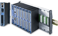
GE Vernova’s MDS I/O Solutions offers Push-In Technology to simplify field wiring of the I/O signals, including an RJ45 interface or an optional fiber interface for digital protocols. The portfolio includes ready to install, configurable options to meet different requirements. Easily install the wall mountable solution into an existing rack or indoor location. In the case of hard to reach places, an enclosure mounted solution may be installed into an existing enclosure or into a new customized MDS-designed enclosure.
Configurable I/O
- 16 DI/DO
- 8 Analog In
- 2 Analog Out
Configuration Simplicity
- Web Interface for easy I/O configuration
- Labeled with circuit diagram
- Push-In Technology for quick assembly
MDS I/O Solutions Application Advantages
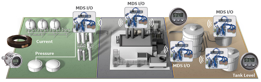

| Water Tank/Well Sites and Wastewater
|
 | Tank Farm Monitoring
|
 | Communications
|
I/O Mirroring
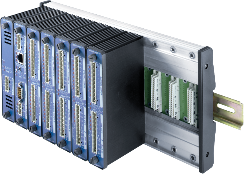
The IOX-M Series platform is designed as both a point-to-point or point-to-multipoint solution for high I/O count systems. The device allows connections of all remote digital and analog input signals from the IOX-R product and converts those signals into output signals to send over a wireless or fiber IP network. The IOX-M series also can I/O mirror up to 26 I/O points from a single location connected to a local Host, PLC or DCS controller at the control center or head end of any system. To reduce field deployment time, the IOX-M series ships preconfigured in 3 different I/O options and ready for install with minimal setup.
For applications that require I/O signal mirroring or splitting from different locations, the IOX-M series can provide the point-to-multipoint I/O mirroring connectivity to collect I/O signals from remote locations and then aggregate them to a single location. The IOX-M series can be custom configured for any I/O combination from any number of remote sites.
| IOX Offering | IOX-MQ | IOX-MH | IOX-MF |
|---|---|---|---|
 | 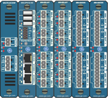 | 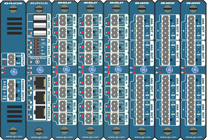 | |
| Total Modules | 4 | 6 | 8 |
| Power Supply Module | 1 | 1 | 1 |
| CPU Module | 1 | 1 | 1 |
| Relay Module | 1 (8 Relays) | 2 (16 Relays) | 3 (24 Relays) |
| Analog Output Module | 1 (4 Analog Outputs) | 2 (8 Analog Outputs) | 3 (12 Analog Outputs) |
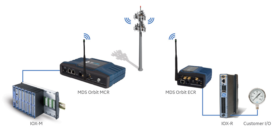 MDS IOx Mirroring System Example
NETio Migration
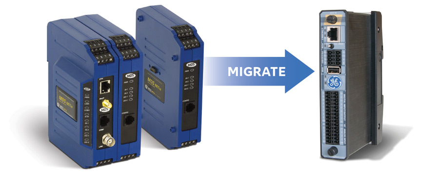
MDS I/O Solutions presents a clear migration for legacy MDS NETio installations. MDS I/O Solutions takes NETio Expansion Modules Types 1-7 and converges them into one solution. These signals can be sent over wireless or fiber communications to the IOX-N module at a local host, PLC or DCS controller. On the edge, the I/O module (IOX-R) offers Modbus TCP to be used for your digital and analog I/O connections.
Upgradeable Simplicity
- Solutions created for 1:1 replacement of NETio products.
- IOX Module programmed for needs
- Web interface for easy I/O configuration
- Push-In Technology for quick assembly
- Force I/O for digital testing
- Force analog inputs / outputs testing
- Communication Status Screen
- Point-to-point I/O Mirroring
Flexible Mounting
- DIN rail
- Rack mount
- Enclosure mountable (sold separately)
- Fiberglass Enclosure either 20x16 or 24x20
- 12, 24, 48, 125 VDC and AC with and without battery backup available
Upgrade your aging NETio systems with MDS IOX Family of Products.
Recommended Products & services
MDS LaunchNET™
Configuration and Provisioning platform
The GE Vernova’s MDS LaunchNET™ configuration and provisioning platform is an automated device provisioning solution that ensures quick and consistent initial device configuration to begin device’s life cycle. It helps minimize deployment errors with coding-free customizable device configuration templates. GE Vernova MDS LaunchNET is currently the ONLY automated software solution for all GE Vernova MDS Orbit devices. Designed for managing and deploying any number of devices with minimal effort in a fully automated and rapid way.
Ease of use and fast provisioning
Intuitive User Interface
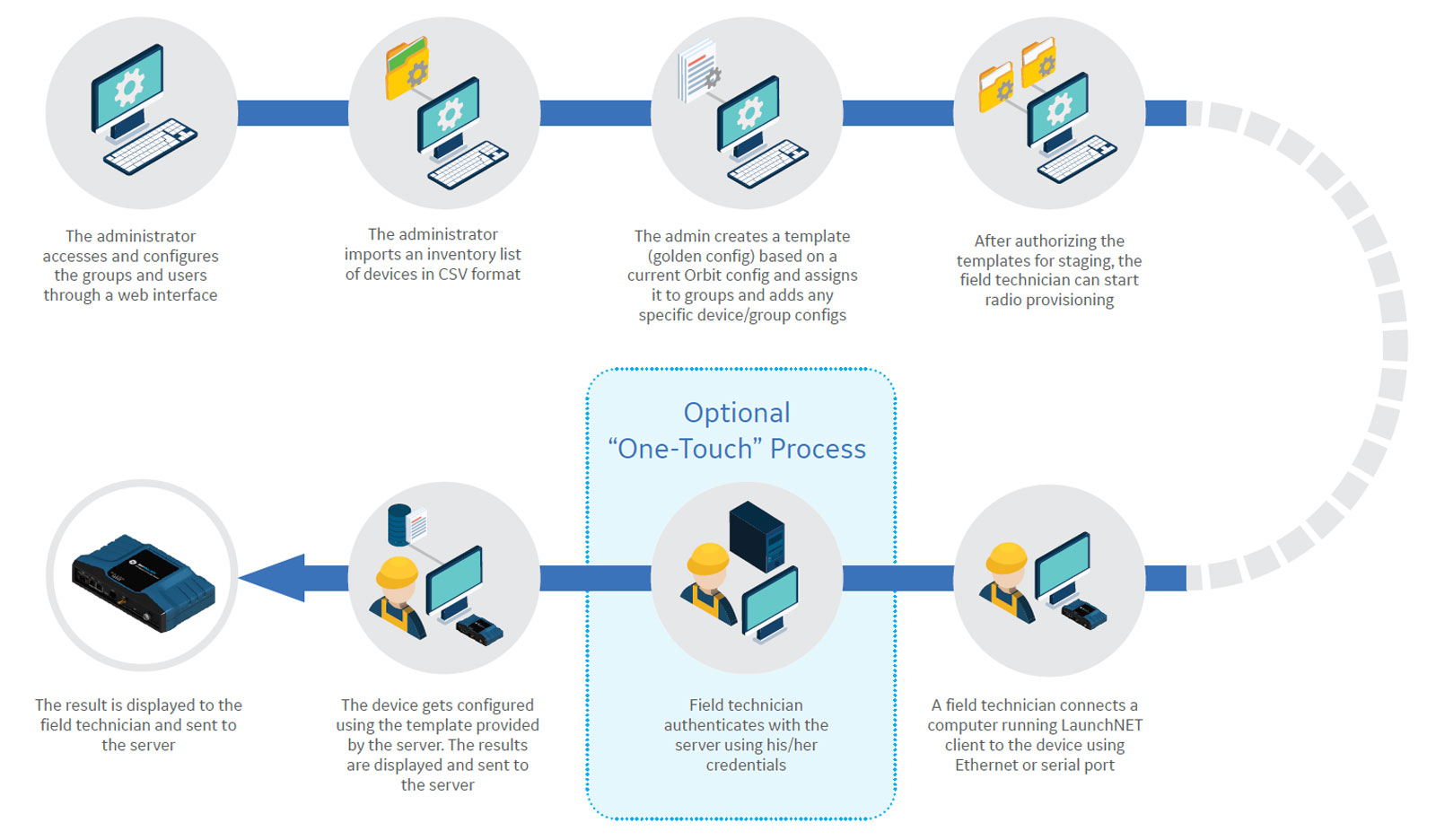
An easy-to-use Graphical User Interface (GUI) that enables management of external interfaces for user authentication using LDAP/Radius and Microsoft PKI for X.509 device certificate enrollment, device inventory database, creation and staging of device configuration templates and viewing deployment reports.
Zero-touch
Zero-touch provisioning driven by device itself. The provisioning can be done in a secure staging environment over a local network and/or in the field over the field network.
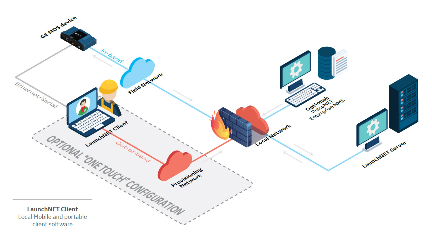
One-touch (In-band or out-of-band)
LaunchNET client can either use the existing network infrastructure for accessing the server (out-of-band) or device’s cellular link for devices equipped with 4G/3G/2G modems. No knowledge is required by the field technician, who only has to enter his/her user authentication credentials in the client software on computer or tablet. The client provides electronic report with the results of the provisioning process.
Lean and intuitive provisioning process
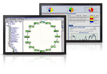
Advanced Network Management for Hardened Optical Multiplexers and PACKET solutions providing:
- A real-time synchronized architecture to meet five 9s.
- High performance engine supports hundreds of users, thousands of network elements, and numerous protocols, all concurrently!
Recommended Products & services
Advanced Network Management
Lentronics™ Advanced Network Management solution is a complete suite of software...
View More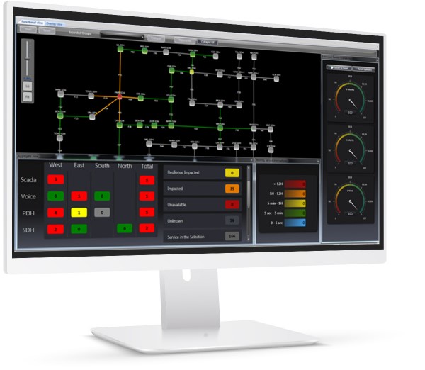
Sentinel 4.0
The challenge power utilities face in implementing their operational communication...
View More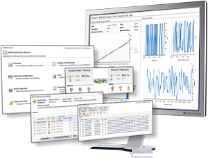
MDS PulseNET
Monitoring and managing the health of your network is a critical consideration when...
View More