EPM 9700
High Performance Power Quality Metering with Advanced Logging and Communications
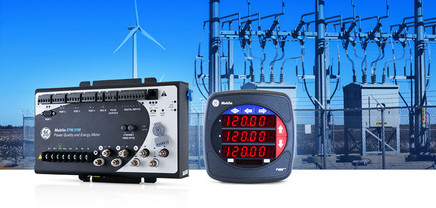
The Multilin™ EPM 9700 is a high performance power quality meter with advanced logging capabilities and flexible communication options. As a member of GE Vernova’s EPM meter family, the EPM 9700 provides a comprehensive picture of power quality and consumption for metered points within an electrical system, empowering users to make power related analysis and decisions quickly and effectively, as well as recording data for accurate reconciliation.
EPM 9700
High Performance Power Quality Metering with Advanced Logging and Communications
The Multilin™ EPM 9700 is a high performance power quality meter with advanced logging capabilities and flexible communication options. As a member of GE Vernova’s EPM meter family, the EPM 9700 provides a comprehensive picture of power quality and consumption for metered points within an electrical system, empowering users to make power related analysis and decisions quickly and effectively, as well as recording data for accurate reconciliation.
EPM 9700 Overview
The EPM 9700 is ideal for revenue and power quality monitoring in a variety of applications, including utility substations, renewables, advanced industrial manufacturing, datacenters and hospitals. It provides a number of key features and benefits, as outlined below.
- Updated IEC 61000-4-30 Class A Edition 3 Power Quality Measurement and EN50160 Reporting Support
- High resolution waveform recording (up to 1024 samples/cycle) and high accuracy 0.06% watt-hour energy metering with demand and time of use capture
- Improved metrology uses high and low gain sensors for high 0.06% accuracy as well as installation flexibility using both 1A and 5A secondary CTs
- Large 1.2GB logging memory makes it possible to log years of captured data
- Easy integration with standard 6 ports (4 serial/2 Ethernet) of flexible communications options and protocol support for simultaneous Modbus and DNP3 communications
- Post installation upgradeable for future requirements with modular communications external I/O and software option functionality upgrades
- Separate meter unit and optional display for flexible and easy installation
- Direct upgrade for EPM 9450/9650 with same wiring/cutout for meter unit/display installation
Accurate Revenue Energy Metering
The EPM 9700 uses advanced high and low gain current sensors for each of the current inputs and determines the optimal sensing circuit for the highest accuracy measurement. This allows the EPM 9700 to have 0.06% accuracy (ANSI Class 0.2%) in an extended measurement range. The wide range pickup of the meter current sensors used also allow the same meter to be used for both 5A and 1A secondary CTs which allows for easier ordering and standardization for multiple applications.
IEC 61000-4-30 Class A Edition 3 Power Quality Meter
- Designed specifically to meet rigorous updated IEC 61000-4-30 Class A Edition 3 standard, the EPM 9700 measures and analyzes power quality metrics precisely
- Reporting available via auto generated EN50160 weekly reporting format
IEC 61000-4-15 Class A Flicker Meter
- Flicker measurements compliant with the IEC 61000-4-15 Class A standard
- Operates on both 220 volt/50 Hz and 120 volt/60 Hz
IEC 61000-4-7 Class A Harmonic and Inter-harmonic Analysis
- View harmonic magnitudes to the 511th order for each voltage and current channel
- Harmonic magnitudes and phase angles in real time are resolved to the 127th order
- Obtain %THD, TDD, and K-Factor
- Conduct power quality analysis at the high end of the harmonic magnitude spectrum
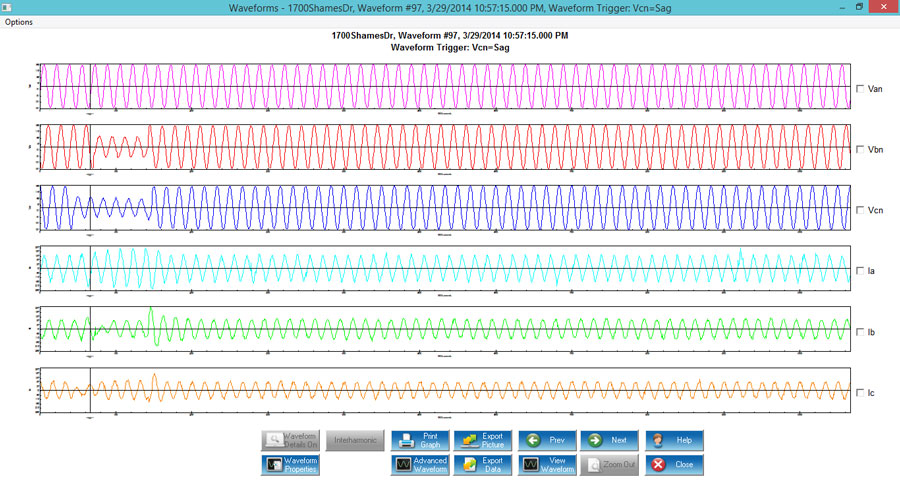
Waveform Recording
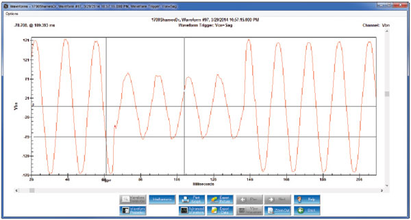
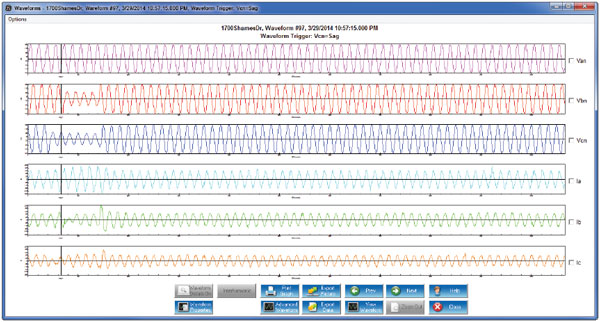
To troubleshoot, remedy and predictively analyze potential system challenges, the EPM 9700 can record waveforms at a sampling rate up to 1024 samples/cycle on multiple power quality events, such as surges and/or sags.
The 16-bit A/D conversion provides precise waveform resolution. Both voltage and current recording offer pre and post-event analysis. Fault recording offers 8 times full-scale capture capability. Both hardware and software triggers are available. GE Vernova Communicator setup software as well as the EPM 9700 web server provides easy remote setup as well as visualization of waveform data.
 Record and Analyze Waveform fault and Transient Data
 Record and Analyze Waveform fault and Transient Data
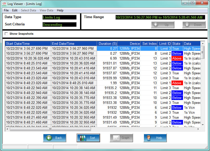
Comprehensive Automated Data Logging
The EPM 9700 meter provides advanced data logging capabilities over time, for trending and analysis. The meter has up to 1.2 GB allocated to logging and user storage, and is also preconfigured to automatically store 142 different measurements (in the CORE™ log) every 15 minutes, without any user intervention. Additionally, a user is able to configure up to 8 historical logs. All logs work with a FIFO buffer and roll over when filled. The EPM 9700 logs important system events such as resets, programming changes, password access changes, time changes power up/down and change of firmware.
- Trending Log: The meter supports up to eight historical, trending logs of 64 data channels per log, acting as a traditional load profile recorder with up to 8 separate logs.
- System Events Security Log: This comprehensive system anti-tampering log records all system events in the meter along with an associated timestamp.
- Control Output Log: This log provides a time-stamped record of relay output changes.
- Input Status Change Log: This log supplies information on the state of the meter’s eight high-speed inputs.
- Limit Log: The Limit/Alarm log can be set to record on high and low conditions for up to 32 user programmable limits.
- Power Quality Log: This log captures power quality events, such as surges and sags, and lets you view and analyze the data through power quality graphs, such as the ITI CBEMA Curve standard.
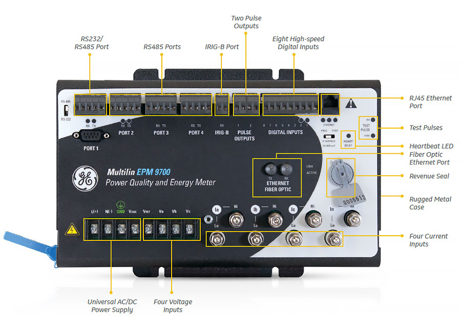
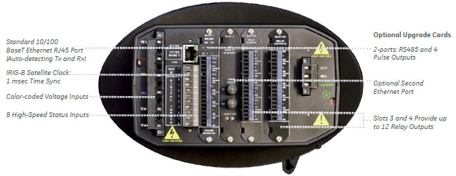
Extensive Communications and I/O
The EPM 9700 meter is equipped with extensive communication capabilities that allow it to speak with many different SCADA or other communication systems, simultaneously. The meter has 6 communication ports as a standard offering. These ports include 4 serial ports and 2 Ethernet-based communication ports. The Ethernet ports include an ST terminated fiber optic port and an RJ45 port. Both ports use separate IP addresses, so that they can run on simultaneous redundant networks.
Details of Ports:
- 6 standard Com ports.
- 4 serial ports - RS485 (one of the ports is RS485/RS232 selectable)
- 2 independent Ethernet ports - RJ45 and Fiber Optic
- Modbus RTU, Modbus ASCII, Modbus TCP/IP, DNP 3.0 Level 2 communication
- All ports can be communicating simultaneously
- Each Ethernet port can be assigned a separate IP address
8 Built-in Digital High-speed Status Inputs:
- Inputs automatically sense whether the circuit is externally wetted
- If externally wetted, input up to 150 VDC is accepted
- If internally wetted, the meter supplies the necessary voltage for the control application
VAUX Input:
- Neutral to ground or aux voltage readings
- Synchronizing schemes, for example, obtaining the frequency, magnitude, and phase angle on both sides of a switch or between generator and bus voltage
Two Standard Pulse Outputs:
- Solid State, form-A, 35 ohm max on resistance
- 120 mA continuous, 350 mA max for 10 ms
- Peak voltage: 350 V DC
- Switching rate max: 10/s
- Support pulse-counting applications
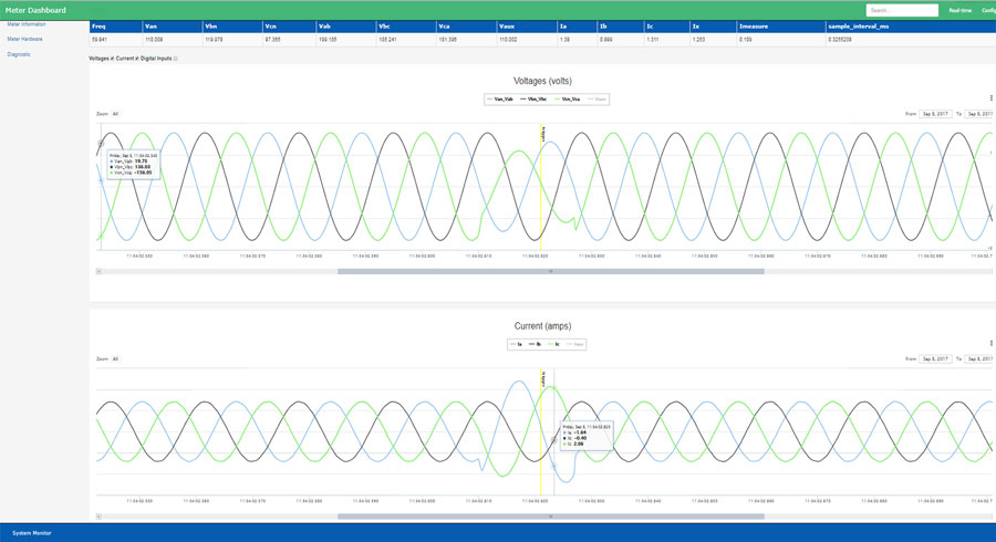
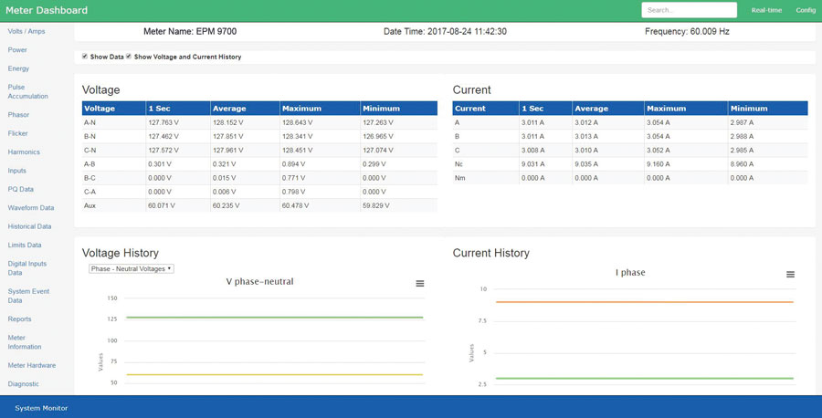
WebView Energy Dashboard
The EPM 9700 supports direct remote Energy and Power Quality Data visualization through an enhanced HTML 5 based web server which provides response formatting, browser based access on a multitude of devices including tablets, phones and workstations. The enhanced web server eliminates the need for additional hardware and/or software to access data on the particular meter remotely.
The visualization includes an Energy Dashboard providing users with easy to understand graphical real time data, as well as to analyze stored historical logs, alarms, and waveform records.
Using the WebView™ Energy Dashboard, the user is able to navigate easily through multiple webpage views, to view a multitude of detailed information on energy usage and power quality such as:
- Detailed charts and graphical trending of real time energy, voltage and current readings to compare past and present values
- Energy usage including tables for demand and usage along with quadrant energy charts
- Phasor readings and a graphical phasor chart
- Waveform event records, including functionality for zoom and pan for detailed visualization and analysis
- Short term (Pst) and Long term (Plt) Flicker readings
- Detailed information for status of digital inputs, KYZ accumulators/aggregators.
- Detailed log information/status
- Meter and diagnostic Information for meter applications and troubleshooting
 Meter and diagnostic Information for meter applications and troubleshooting
Recommended Products & services
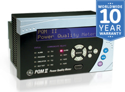
PQM II
The PQM II is an ideal choice when continuous monitoring of a three phase system is...
View More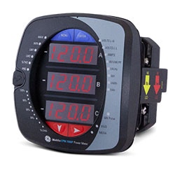
EPM 7000P
The Multilin™ EPM 7000P is a versatile power quality meter offering that can be used...
View More
EPM 7000 Power Quality Meter
The EPM 7000 provides continuous metering of three-phase systems with waveform and data...
View MoreEPM 9900P
High Performance Power Quality and Transient Recorder Meter
The Multilin™ EPM 9900P is one of Multilin’s most advanced power quality meters and provides comprehensive perspective of energy usage; capture of power quality events and easy integration with support for multiple protocols to provide key decision making and monitoring information for critical energy circuits in utility substation or industrial applications.
EPM 9900P
High Performance Power Quality and Transient Recorder Meter
The Multilin™ EPM 9900P is one of Multilin’s most advanced power quality meters and provides comprehensive perspective of energy usage; capture of power quality events and easy integration with support for multiple protocols to provide key decision making and monitoring information for critical energy circuits in utility substation or industrial applications.
Features
Communications
- Modbus, DNP 3.0, IEC 61850 (including high speed GOOSE messaging), SNMP, IEC 1588 PTPv2 and IEEE 37.118.2-2011
- Standard Ethernet communications port with dual Ethernet capability
- Port control to secure and disable services/ports
- Easy system integration supporting up to 32 Modbus TCP/IP sockets per Ethernet port along with configurable Ethernet port services for security
Measuring and Metering
- 0.06% Energy Accuracy (ANSI 0.2%)
- IEC 61000-4-30 Power Quality Class A Ed. 3 and EN50160 Reporting Support
- Available 50MHz Transient Recorder (over 800,000 samples/cycle)
- Phasor Measurement Unit (PMU) Capability
- Harmonics up to the 511th order (Voltage,Current), 127th order in real time
- Voltage Sag/Swell, Current Fault and Transient Recording
- Up to 4 GB data logging
High Performance Power Quality and Transient Meter for Utility or Industrial Applications

The EPM 9900P provides revenue accuracy for energy monitoring and high performance power quality analysis functions including harmonics, flicker and transient waveform capture. Power quality reporting data is collected in compliance with IEC 61000-4-30 Class A and EN 50160 international standards providing users a deep understanding in a variety of utility or industrial applications.
With up to 4GB of data logging, including 50 MHz transient capture, the EPM 9900P ensures that essential power quality data and events are captured, stored, and time synchronized allowing for comprehensive analysis of events. The EPM 9900P also supports a multitude of communications protocols such as Modbus, DNP3 and 61850 making it easy to integrate and retrieve data into a SCADA or data analysis system.
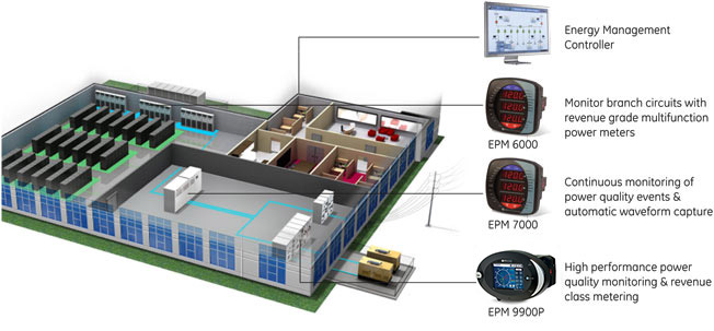
Application Example
Multifunction Metering & Power Quality Monitoring
The EPM 9900P can provide a total picture of power usage and power quality at different points within a power distribution network, allowing users to make power related decisions quickly and effectively.
Class A Power Quality Reporting
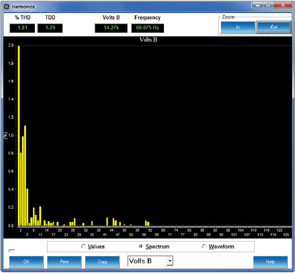 Extensive harmonics analysis capabilities
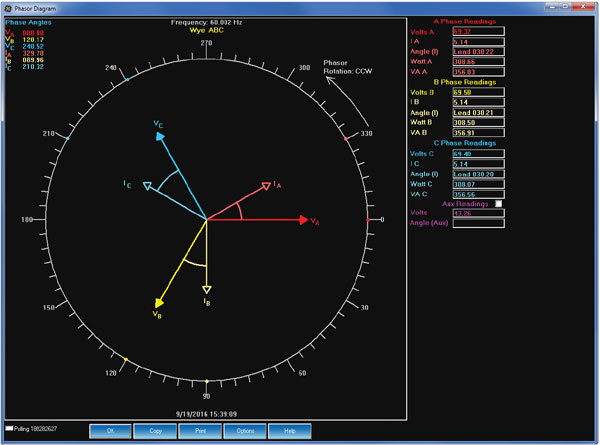 Comprehensive Phasor visualization
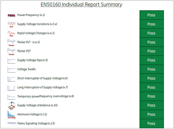 User-friendly reports illustrating PQ compliance
The EPM 9900P captures and stores comprehensive power quality information, including harmonics, sags, swells and transients providing a clear perspective and log of faults and disturbances to allow for detailed and extensive forensic engineering analysis.
IEC 61000-4-30 Class A Ed.3 Power Quality Meter
- Designed specifically to meet the rigorous IEC 61000-4-30 Class A Ed. 3 standard, the EPM 9900P measures and analyzes power quality metrics precisely. 
- All reporting is available via the EN 50160 reporting format which can be further customized to meet the required application or regulatory needs.
IEC 61000-4-15 Class A Flicker Meter
- Flicker compliant with the IEC 61000-4-15 Class A standard 
- Operates on both 220 volt/50 Hz and 120 volt/60 Hz throughout standard test points
IEC 61000-4-7 Class A Harmonics and Interharmonics Analysis
- View harmonic magnitudes to the 511th order for each voltage and current channel 
- Harmonic magnitudes and phase angles in real time are resolved to the 127th order 
- Obtain %THD, TDD, and K-Factor 
- Conduct power quality analysis at the high end of the harmonic magnitude spectrum 
Phasor Analysis
The monitor reads a phase angle analysis between the voltage and current channels, allowing you to analyze efficiency and system integrity.
High-speed Voltage Reliability Measurements
The EPM 9900P meter provides industry leading voltage measurement.
- Real time single cycle RMS measurements
- Customizable high-speed readings – can be set from 2 to 20 cycles RMS
Set Limit Control
Programmable setpoints allowing a user to configure the meter to be used as a control device for many applications, such as:
- Capacitor control
- Load shedding
- Automatic transfer schemes
- Transformer monitoring & control
- Redundant protection (not designed for primary over-current protection)
- Many other control functions
Alarm Notification
The EPM 9900P meter lets you set multiple programmable limits for any measured value, as well as those set up in a Boolean logic tree, and limits set up in the IEC 61850 protocol implementation. Users can be notified of alarm conditions via email.
16 Bit Waveform and Fault Recorder
- Record up to 1024 samples per cycle; capture a transient at over 800,000 samples per cycle or at 50 MHz sampling speed
- Voltage and current recording with pre and post-event analysis
- Fault recording offers 8 times full scale capture capability
- 16 bit A/D converter provides precise waveform resolution
- Both hardware and software triggers are available
High-speed Status Input Triggers
- Waveforms are recorded at time of status change
- Input change and waveform recording are time-stamped to a 100 micro second resolution
- Inputs and waveforms can be displayed together to time breakers and relays
Subcycle 50 MHz Transient Recorder (Software Option C)
A user can define log sizes within the meter. Thus the full memory can be allocated specifically to the desired function.
Independent ITIC/CBEMA Log Plotting
- Quickly view total surges, sags, and average duration in the independent ITIC/CBEMA log
- SEMI F47 graphing for power quality compliance in semiconductor industry
Compatible Waveform Formats
Using GE Vernova Communicator software, the meter will provide all waveform data via COMTRADE and PQDIF compatible formats. This allows the waveform PQ and fault records to be read by most third-party waveform analysis software programs.
- COMTRADE (common format for transient data exchange) is defined by IEEE Std C37.111
- PQDIF (power quality data interchange format) is defined by IEEE Std 1159.3-2003
Record Phasor Measurement Unit (PMU) Data for Analysis
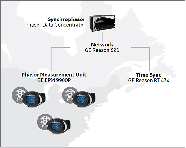
The EPM 9900P meter has been enhanced with Phasor Measurement Unit (PMU) functionality meeting the IEEE C37.118.1a-2014 standard. A PMU device measures time-synchronized, phasor (magnitude and phase angle of voltage and current) and related data from a specific location on the electrical grid. The data from multiple PMUs are transmitted to a phasor data concentrator (PDC), which aggregates and time-aligns the data for real time and post analysis.
Collection of Synchrophasor data is useful in applications such as:
- Aggregation of instantaneous, time synchronized voltage, current, and frequency at specific locations on the grid for easy greater wide-area system operator situational awareness
- Determination of stress points of the utility transmission system
- Detect and aid in restoration an islanded section of the grid after a storm or major outage disturbance
- Collection and integration of PMU data for visualization in an Energy Management System (EMS).
EPM 9900P Synchrophasor Features
- Supports both P and M classes
- Time sync standard: IRIG-B or IEEE 1588 PTPv2
- Calculates individual voltage/current phasors, symmetrical components’ phasors, frequency, rate of change of frequency, the meter’s high-speed digital inputs, analog fundamental power, and displacement power factor
- Data frame rates:
- 50 Hz - 10/25/50 frames per second
- 60 Hz - 10/12/15/20/30/60 frames per second
- Data format: configurable float or integer, polar or rectangular
- Support for up to two simultaneous clients with Ethernet or Fiber over Ethernet communication
Easy System Integration and Available IEC 61850 Solution
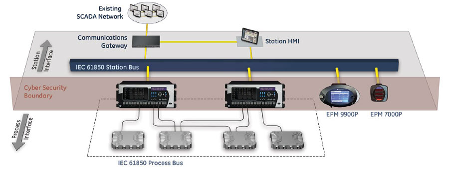
Software options B and above offer an embedded IEC 61850 Protocol Server for seamless integration with substation automation and industrial 61850 applications.
- The IEC 61850 Protocol Server allows up to 6 simultaneous MMS clients.
- Either Ethernet port can be configured for IEC 61850 (only one port at a time can run IEC 61850)
- GOOSE publisher/subscriber functionality is supported.
- Buffered and unbuffered reports are supported for the following triggers: general meter interrogation, for example, the report is generated in response to a query; meter integrity, for example, the report is generated according to a programmed interval; and data change, for example, the report is generated due to a change in the contents of a dataset.
- File transfer is supported
- Embedded Web Protocol Server support is available for IEC 61850 CID file uploading, IEC 61850 Protocol Server status and for displaying incoming and outgoing GOOSE messages.
- Multiple Logical Nodes, which map flicker, harmonics, digital inputs/outputs, limit state, voltage, current, energy and other data, are supported.
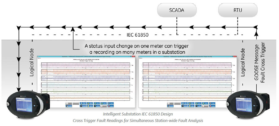
- Waveform capture can be triggered by status input data inside GOOSE messages. The user can program up to 16 status inputs that will trigger a waveform capture when the information is received via a GOOSE message. The status inputs include digital inputs, limit states, and any other status input supported by the meter.
Unique GOOSE Cross Trigger
- Fault-based cross trigger of waveform based on GOOSE message
- Provides system-wide distribution fault analysis on an event
- Timing better than 200 microseconds is typical
- Many different circuits can be viewed after an event occurred
Flexible Communications Options
The EPM 9900P meter offers up to 6 simultaneous communication ports and multiple protocols to meet almost every need.
Hardware Features:
- 2 optional RS485 ports speaking Modbus and/or DNP 3.0
- USB front panel port
- ANSI optical front panel port
- 2 separately addressable Ethernet ports
- Optional Fiber or RJ45 media on one Ethernet port
Ethernet Communication Port Capabilities
- 2 Ethernet ports provide multiple simultaneous communication
- Each port has separate MAC address and IP address
- Supports Modbus TCP/IP, DNP 3.0 and IEC 61850
- GOOSE messaging protocol supported for IEC 61850
- Up to 32 Modbus TCP/IP sockets per Ethernet port
- Highly secure port control to disable unneeded services and ports
- Email Function - SMTP email to client on alarm
- Precise Time Synchcronization - SNTP Time Sync protocol
- File Transfer Protocol - High-speed file data transfer
- Support for IEEE 1588 PTPv2 for critical time sync applications, e.g., synchrophasor systems.
- IEEE C37.118.2 PMU communication
Industry-Leading DNP 3.0 Level 2 Plus – Complies with DNP Level 1 and Level 2 Certification Requirements
- Up to 136 measurements (64 Binary Inputs, 8 Binary Counters, 64 Analog Inputs) can be mapped to DNP static points
- Up to 16 relays and 8 resets can be controlled through DNP
- Report-by-exception processing (DNP Events) deadbands with unsolicited response for serial communication
- 250 available events, in four event types (Binary Input Change, Frozen Counter, Counter Change, and Analog Change)
SNMP Protocol
SNMP protocol V1 and V2 are supported for managed device networks (i.e. Data center network applications) Features include:
- Support for 40+measurements
- Traps for limits, input change, and power quality
- Cold start trap and authentication failure supported
8 Built-in Digital High-speed Status Inputs
- Inputs automatically sense whether the circuit is externally wetted
- If externally wetted, input up to 150 VDC is accepted
- If internally wetted, the meter supplies the necessary voltage for the control application
VAUX Input
- Neutral to ground or aux voltage readings
- Synchronizing schemes, for example, obtaining the frequency, magnitude, and phase angle on both sides of a switch or between generator and bus voltage
Multilin Meter Enclosure
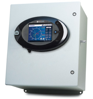
Expanding existing switchgear or installing new metering capability can be challenging due to space limitations, downtime and installation and equipment costs. GE Vernova’s Multilin Meter Enclosure is a pre-wired configured, economical solution for both retrofit expansions and small scale meter installations that allows the expansion of existing switchgear capability without expensive and time-consuming design.
When ordered as a meter option the enclosure provides a factory pre-wired, installation-ready metering solution that further drives energy cost savings, by enabling the measurement of key energy usage information along multiple metering points for new or existing systems. Ordering the enclosure is simple when selected as an option during meter configuration, ensuring correct pre-wired meter-compatible delivery.
Pre-Wired, Configured and Economical Solution for Retrofit and Small Metering Systems
Easy and Rapid Installation
- Factory pre-wired, installation-ready GE Vernova metering solution eliminates wiring and associated errors for rapid installation
- Extend metering capability with new systems and existing switchgear without system installation downtime
Cost-Effective Retrofit Solution
- Save up to 200% versus the addition of a new switchgear cabinet
- Compact footprint makes effective use of existing allocated space
- Allows new installations or the expansion of existing switchgear capability without expensive, time-consuming designs, eliminating system downtime
Reliable and Compatible
- Backed by a 10 year warranty
- Simple meter option ordering ensures compatibility with GE Vernova EPM 9900P meters
- Comprehensive factory testing of both meter and enclosure together
- NEMA1 tested and UL/CUL certified
Applications (New and Retrofit installations)
- Utility/Indusrial Power Quality Studies
- Healthcare Institutions
- Government Buildings
- Manufacturing
- Educational Campuses
- Data Centers
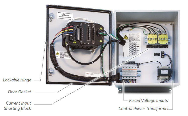
Meter Enclosure Assembly
The installation of the GE Vernova’s Multilin Meter Enclosure is simple, safe and eliminates downtime through simple mounting and wiring. The enclosure is UL/CUL certified and NEMA 1 rated making it ideal for indoor environments.
It is provided in two voltage configurations (120-240V and 277V) to ensure compatibility with customer installations. The standard equipment includes voltage fuses; a shorting block for current transformers; and a control power transformer for 277V power systems that are pre-wired and configured to ensure safety, quality and long-term reliability.
Software Options
The EPM 9900P provides software options to meet specific power quality measurement functionality as well as logging, sampling and communications requirements.
The software options are also upgradeable after purchase/installation. This provides flexibility to expand functionality for future requirements or budgetary approval.
| FEATURE | A | B | C | D | E | F |
|---|---|---|---|---|---|---|
| Basic Measurements | • | • | • | • | • | • |
| Memory | 512 MB | 1GB | 4GB | 512 MB | 1GB | 4GB |
| Sampling Speed (samples/cycle) | 512 | 1024 | 1024 | 512 | 1024 | 1024 |
| 50 MHz Transients | • | • | ||||
| IEC 61000-4-30 Class A Edition 3 | • | • | • | • | • | • |
| IEC 61850 Server | • | • | • | • | ||
| IEC 61850 GOOSE | • | • | • | • | ||
| CyberSecurity | • | • | • | |||
| Synchrophasor PMU | • | • | • |
Technical Specifications
| INPUT VOLTAGE RANGE |
|---|
|
| VOLTAGE INPUT WITHSTAND CAPABILITY |
|---|
|
| INPUT CURRENT RANGE |
|---|
|
| CURRENT INPUT WITHSTAND CAPABILITY (AT 23 °C) |
|---|
|
| BURDEN |
|---|
|
| ISOLATION |
|---|
|
| TEMPERATURE RATING |
|---|
|
| SENSING METHOD |
|---|
|
| ACCURACY RATING |
|---|
|
| UPDATE TIME |
|---|
|
Note: Please see product User Manual for comprehensive specifications.
| CONTROL POWER REQUIREMENTS |
|---|
|
| FREQUENCY RANGE |
|---|
|
| COMMUNICATION FORMAT |
|---|
|
| SHIPPING |
|---|
|
| COMPLIANCE |
|---|
|
Recommended Products & services
PQM II
The PQM II is an ideal choice when continuous monitoring of a three phase system is...
View More
EPM 7000P
The Multilin™ EPM 7000P is a versatile power quality meter offering that can be used...
View More
EPM 7000 Power Quality Meter
The EPM 7000 provides continuous metering of three-phase systems with waveform and data...
View MoreAnalise
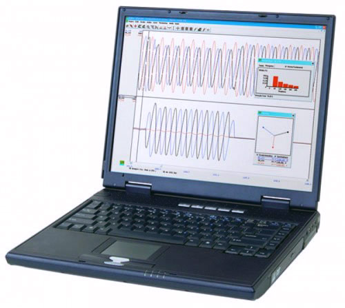
Visualization and Analysis of Oscillographic Records
Analise is an application developed by Reason Tecnologia for graphic visualization, handling and analysis of oscillographic records. Analise works with the worldwide IEEE COMTRADE standard format (Common Format for Transient Data Exchange) IEEE C37.111-1991, 1996 and IEEE C37.111-1999.
Analise is an application developed by Reason Tecnologia for graphic visualization, handling and analysis of oscillographic records. Analise works with the worldwide IEEE COMTRADE standard format (Common Format for Transient Data Exchange) IEEE C37.111-1991, 1996 and IEEE C37.111-1999.
Analise
Visualization and Analysis of Oscillographic Records
Analise is an application developed by Reason Tecnologia for graphic visualization, handling and analysis of oscillographic records. Analise works with the worldwide IEEE COMTRADE standard format (Common Format for Transient Data Exchange) IEEE C37.111-1991, 1996 and IEEE C37.111-1999.
Analise is an application developed by Reason Tecnologia for graphic visualization, handling and analysis of oscillographic records. Analise works with the worldwide IEEE COMTRADE standard format (Common Format for Transient Data Exchange) IEEE C37.111-1991, 1996 and IEEE C37.111-1999.
Recommended Products & services
Analise
Analise is an application developed by Reason Tecnologia for graphic visualization,...
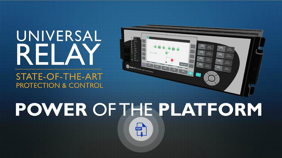
View MoreMultilin N60
Network Stability and Synchrophasor Measurement System
The N60 network stability and synchrophasor measurement system is a flexible device intended for the development of load shedding, remedial action, special protection schemes and wide area monitoring and control. Like no one device before, the N60 shares real-time operational data to remote N60s so the system can generate intelligent decisions to maintain power system operation.
Multilin N60
Network Stability and Synchrophasor Measurement System
The N60 network stability and synchrophasor measurement system is a flexible device intended for the development of load shedding, remedial action, special protection schemes and wide area monitoring and control. Like no one device before, the N60 shares real-time operational data to remote N60s so the system can generate intelligent decisions to maintain power system operation.

New and Enhanced Communication Capabilities
- New process bus module supports IEC 61869 sample values, PTP master capabilities and SV switching (FW 7.9x)
- New UR process bus modules supporting IEC61850-9-2LE Merging Units (FW 7.8x) Module Training available here
- Support switchable IEC 61850 Ed. 1 and Ed. 2 and redundant SNTP (FW 7.7x)
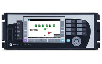
- New UR front panel with integrated 7” color, graphical display - providing operators with enhanced situational awareness (FW 7.6x)
- High density I/O module supporting up to 120 inputs or up to 72 contact outputs – eliminating the need for additional discrete devices (FW 7.6x)

Cyber Security - CyberSentry UR (FW v7.xx)
CyberSentryTM enables UR devices to deliver full cyber security features that help customers to comply with cyber security requirements (NERC CIP, IEEE 1686, IEC 62443, etc):
- Secured firmware upgrade: FW file includes hash code that enables authentication prior to being used for upgrading UR Relay (FW 7.9x)

Fully Compatible with IEC 61850-9-2LE or IEC61869 process bus schemes:
- Can connect to up to 8 merging units over -9-2LE or 61869
- Supports PRP, HSR, dual HSR and point-to-point process bus topology
- Provides support for GE Vernova’s IEC 61850 HardFiber Process Bus Solution

Extended Oscillography Records (FW v7.xx)
- Increased number of digital and analog channels (FW 7.90)
- Supports IEEE C37.111-1999/2013, IEC 60255-24 Ed 2.0 COMTRADE 2013 standard (FW v7.40)
- Configurable events allow for records of up to 45s at 64 samples per cycle

New and Enhanced Protection and Control Functionality
- New Inrush detection element (FW 8.0)
- Expanded Bay Controller Capabilities – providing a one box solution (FW 7.6x)
Key Benefits
- Underfrequency, overfrequency, rate of change of frequency (df/dt)and dedicated harmonic/inrush detection
- Out-of-step tripping and power swing blocking
- Thermal overload and phase instantaneous overcurrent
- Synchrocheck
- Overvoltage, undervoltage
- FlexMath for performing automated network control for applications such as automatic load shedding, power balancing and remedial action schemes
ANSI® Device Numbers & Functions
|
|
|
Key Features
- Phasor Measurement Unit (synchrophasor) according to IEEE® C37.118 (2014) and IEC® 61850-90-5 support
- High-speed reporting 120fps (Pclass)
- Magnitude and phase calibration
- Dual reporting (P & M class simultaneously)
- Aggregation capabilities
- Multiple configurable PMU elements (up to 6)
- PMU recording configurable (46 channels)
- Extended protection and control features
- Data Logger – Up to 16 channels with sampling rate up to 1 sample/cycle
Monitoring & Diagnostics
The N60 includes high accuracy metering and recording for all AC signals. Voltage, current, and power metering are built into the relay as a standard feature. Current and voltage parameters are available as total RMS magnitude, and as fundamental frequency magnitude and angle.
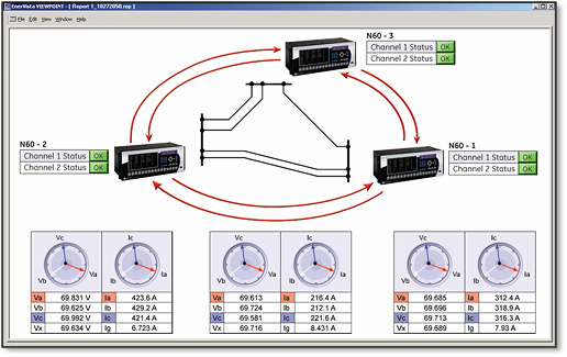 The N60 is the single point for protection, control, metering, and monitoring in one integrated device that can easily be connected directly into DCS or SCADA monitoring and control systems like Viewpoint Monitoring as shown.
FlexLogic™
FlexLogic is the powerful UR-platform programming logic engine that provides the ability to create customized protection and control schemes based on information measured locally by the N60 and received from remote N60s sent to it over the communications network. With FlexLogic, the N60 can use the status of measured inputs, along with the output of the protection elements, FlexElements and FlexMath summators, in Boolean logic equations to perform automated functions for customized special protection schemes.
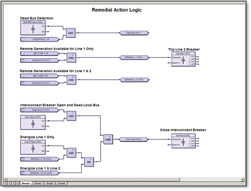 The N60 contains FlexLogic and FlexMath equations that allow the creation of automated wide area protection and control schemes, remedial action schemes, and other special protection applications.
Key Features
Complete IEC 61850 Process Bus solution providing resource optimization and minimizing total P & C life cycle costs
- Three independent 100Mbps Ethernet ports enable purpose specific LAN support that eliminates latency effect of heavy traffic protocols on mission critical communication services
- Embedded IEEE 1588 time-synch protocol support eliminates dedicated IRIG-B wiring requirements for IEDs
- Direct I/O secures high-speed exchange of binary data between URs
- Increase network availability by reducing failover time to zero through IEC62439-3 PRP, HSR or dual HSR support
Advanced Communications
The N60 provides advanced communications technologies for remote data and engineering access, making it the easiest and most flexible Motor protection relay to use and integrate into new and existing infrastructures. Direct support for fiber optic Ethernet provides high-bandwidth communications allowing for low-latency controls and high-speed file transfers of relay fault and event record information. The available three independent and redundant Ethernet options provide the means to create fault tolerant communication architectures in an easy, cost-effective manner.
The N60 supports the most popular industry standard protocols enabling easy, direct integration into DCS and SCADA systems.
- IEC 61850-9-2LE networked or IEC 61869 point-to-point or networked or IEC61850-9-2 Hardfiber process bus support
- DNP 3.0 (serial & TCP/IP)
- IEC 60870-5-103 and IEC 60870-5-104
- Modbus RTU, Modbus TCP/IP
- HTTP, TFTP, SFTP and MMS file transfer
- Redundant SNTP and IEEE 1588 for time synchronization
- PRP as per IEC 62439-3
- Supports Routable GOOSE (R-GOOSE)
Interoperability with Enbedded IEC 61850
Use the N60 with integrated IEC 61850 to lower costs associated with generator protection, control and automation. GE Vernova’s leadership in
IEC 61850 comes from thousands of installed devices and follows on years of development experience with UCA 2.0.
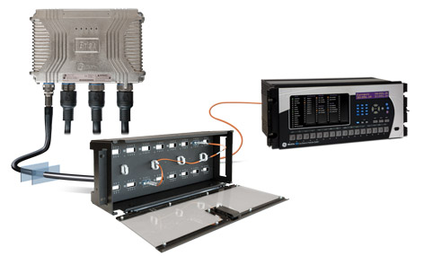
The N60’s IEC 61850 Process Bus module is designed to interface with the Multilin HardFiber System, allowing bi-directional IEC 61850 fiber optic communications. The HardFiber System is designed to integrate seamlessly with existing Universal Relay applications, including protection functions, FlexLogic, metering and communications. Learn More
The N60 can also connect to GE Vernova MU320 or third-party merging units using standard IEC 61869 or IEC 61850-9-2LE communication protocols.
Cyber Security - CyberSentry™ UR (FW v7.4xx)
CyberSentry enables UR devices to deliver full cyber security features that help customers to comply with NERC CIP and NITIR 7628 cyber security requirements through supporting the following core features:
Password Complexity
Supporting up to 20 alpha- numeric or special characters, UR passwords exceed NERC CIP requirements for password complexity. Individual passwords per role are available.
AAA Server Support (Radius)
Enables integration with centrally managed authentication and accounting of all user activities and uses modern industry best practices and standards that meet and exceed NERC CIP requirements for authentication and password management.
Role Based Access Control (RBAC)
Efficiently administrate users and roles within UR devices. The new and advanced access functions allow users to configure up to five roles for up to eight configurable users with independent passwords. The standard “Remote Authentication Dial In User Service” (Radius) is used for authentication.
Event Recorder (Syslog for SEM)
Capture all cyber security related events within a SOE element (login, logout, invalid password attempts, remote/local access, user in session, settings change, FW update, etc), and then serve and classify data by security level using standard Syslog data format. This enables UR devices integration with established SEM (Security Event Management) systems.
EnerVista™ Software
The EnerVista™ suite is an industry-leading set of software programs that simplifies every aspect of using the N60 relay. The EnerVista™ suite provides all the tools to monitor the status of the protected asset, maintain the relay, and integrate information measured by the N60 into DCS, SCADA monitoring or WAM systems. Convenient COMTRADE and Sequence of Events viewers are an integral part of the UR setup software included with every UR relay, to carry out postmortem event analysis and ensure proper protection system operation. Learn More
Recommended Products & services
Multilin N60
The N60 network stability and synchrophasor measurement system is a flexible device...
View MoreReason RPV311
Digital Fault Recorder with PMU and TWFL
Reason RPV311
Digital Fault Recorder with PMU and TWFL
Recommended Products & services

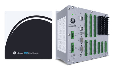
Reason DR60
Compact Digital Fault Recorder
Reason DR60
Compact Digital Fault Recorder
Recommended Products & services
Reason MU320E
Process Interface Unit with integrated analog and digital merging interfaces
MU320E is the Process Interface Unit (PIU) with analog and binary interfaces for full switchyard modeling, control and digitalization over IEC 61850 standards & protocols such as Sampled Value (SV) and GOOSE.
Reason MU320E
Process Interface Unit with integrated analog and digital merging interfaces
MU320E is the Process Interface Unit (PIU) with analog and binary interfaces for full switchyard modeling, control and digitalization over IEC 61850 standards & protocols such as Sampled Value (SV) and GOOSE.
Recommended Products & services
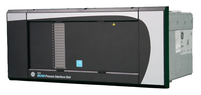
MU360
MU360 is the Process Interface Unit (PIU) with analog and binary interfaces for full...
View More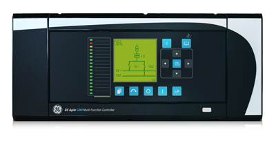
MiCOM C264
GE Vernova’s MiCOM C264 bay controller provides flexibility, reliability and ease of...
View More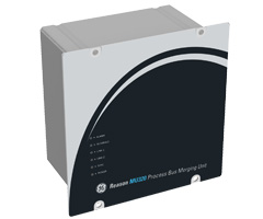
Reason MU320E
MU320E is the Process Interface Unit (PIU) with analog and binary interfaces for full...
View MoreMiCOM C264
Bay Controller
GE Vernova’s MiCOM C264 bay controller provides flexibility, reliability and ease of use. A combination of dual redundant fiber optic Ethernet, modular I/O, and an expandable design and extensive library of functions make the C264 the ideal solution for a wide array of applications in substation digital control systems.
MiCOM C264
Bay Controller
GE Vernova’s MiCOM C264 bay controller provides flexibility, reliability and ease of use. A combination of dual redundant fiber optic Ethernet, modular I/O, and an expandable design and extensive library of functions make the C264 the ideal solution for a wide array of applications in substation digital control systems.
What's New
Overview
The DS Agile C264 substation controller is a sophisticated solution supporting multiple applications and functions for substation control, communication, monitoring, protection, and automation. Flexibility, reliability and ease of use are among the top features required in a substation computer; the latest release of DS Agile C264 has these features and is equipped with a new generation CPU (CPU4v2) compatible with 64 Bits technology.
A combination of dual redundant fiber optic Ethernet, modular I/O, expandable design, and an extensive library of functions make the C264 the ideal solution for a wide array of applications in substation digital control systems.
Key Benefits
- Flexible, modular and expandable design to support many applications
- Dual-bay management with two embedded CT/VT acquisition boards including measurements and sampled values streams to reduce the number of controllers
- Back up protection function
- New 64 Bits processor that allows virtual address ranges greater than 4GB in size
- HSR/PRP RedBox capability to connect PRP/HSR non-compliant devices to the redundant network, reducing the number of RedBoxes
- Reduce engineering costs and amount of devices, wiring, cabling and training required by using the multi-functional capabilities
- IEC 61850-8-1 and IEC 61850-9-2 standard compliance for interoperability
- LCD graphical display for user-friendly local control, monitoring and maintenance
- Seamless integration with existing substation assets with flexible interfaces, expandability and support of legacy and cutting-edge communication protocols
- Proven solution with more than 50,000 units installed worldwide
Applications
- Full digital substation and conventional substation
- Transmission, distribution, utilities and industrial
- Green field and brown field substation
Two models are available within the C264 Bay Controller range:
C264 CPU3 Please contact GE Vernova to check availability for brownfield applications. Note: GE Vernova has confirmed order book closed for greenfield applications on 31st May 2024. As an alternative, please refer to C264 CPU4.
C264 CPU4 remains available, with more processing power and memory capacity than CPU3, it has 6 Ethernet ports supporting protocols for redundant networking architecture. Enabled to communicate through several protocols and with flexibility to incorporate complex IEC 61131-3 soft logics.
DS Agile SCE
Key benefits:
The Configuration tool SCE is defined to handle all system structured data and to generate databases loaded on DS Agile System main equipment:
- DS Agile aView, the system HMIs
- DS Agile SMT, the System Management Tool that download databases
- DS Agile Gateway, the separate Tele-control Interface to the SCADA
- DS Agile C26x controllers (Bay Control Units, Protection and Control Units, Remote Terminal Units)
Engineering tool suite
The tool is designed to be used for several system pieces of equipment working together with their exchange communication data, or only one of them. For example, it can generate the database of a DS Agile C26x Standalone RTU.
The DS Agile SCE applications are mainly defined in the Application chapter (AP) of each DS Agile sub-system (DS Agile C26x, DS Agile Gateway). DS Agile aView configuration is described in the DS Agile Blend & Mimic Designer manual (Application chapter for the SCE part).
The Black/Silver front panel is offering a USB connector, the Virtual COM port (VCP) drivers from FTDI Chip manufacturer need to be installed.
Recommended Products & services
MU360
MU360 is the Process Interface Unit (PIU) with analog and binary interfaces for full...
View More
MiCOM C264
GE Vernova’s MiCOM C264 bay controller provides flexibility, reliability and ease of...
View More
Reason MU320E
MU320E is the Process Interface Unit (PIU) with analog and binary interfaces for full...
View MoreMultilin D.20 I/O Modules
GE Vernova’s classic D.20 I/O Modules are input/output modules for substation automation and SCADA RTU applications. They have stood the test of time, continue to be widely used, and are extremely reliable. Connecting to G100, G500, D400 (with D.20 RIO), and D20MX, the D.20 I/O Modules provide local, remote, and distributed physical I/O capabilities for digital and DC analog data collection and substation control.
D20 I/O options
Multilin D.20 I/O Modules
GE Vernova’s classic D.20 I/O Modules are input/output modules for substation automation and SCADA RTU applications. They have stood the test of time, continue to be widely used, and are extremely reliable. Connecting to G100, G500, D400 (with D.20 RIO), and D20MX, the D.20 I/O Modules provide local, remote, and distributed physical I/O capabilities for digital and DC analog data collection and substation control.
D20 I/O options
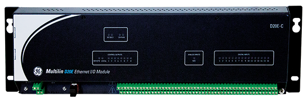
Multilin D20E
Advanced Substation I/O Modules
The Multilin D20E is the next-generation input/output (I/O) module for substation automation and SCADA RTU applications, ideal for D20 I/O upgrade. As a non-edge device leveraging the latest technology in microprocessors, communications and applications, the D20E I/O can be deployed within an electronic security perimeter such as with a server (e.g. D20MX or D400) or with IEDs.