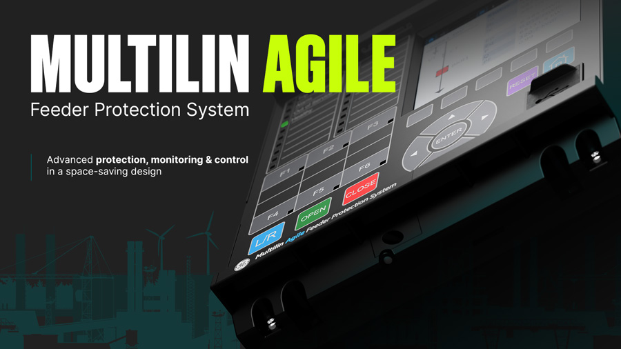
Multilin Agile
Compact Feeder Protection and Bay Controller
GE Vernova’s Multilin Agile Feeder Protection solution offers advanced protection, monitoring, and control for utilities, industrial plants, onshore and offshore renewable collectors, and more. Serving as primary or backup feeder protection, it is equipped with advanced communication options and extensive monitoring capabilities.
What is Multilin Agile?
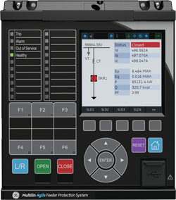
Multilin Agile is a compact feeder protection and bay controller device with extensive protection, control, and communications capabilities. The design ensures that performance, sensitivity, customization, and flexibility are delivered along with minimized configuration and commissioning effort. The device is configured using software with few order code variants, providing standardization that mitigates the risk of mis-ordering, enables easy stocking, and reduces spare inventory.
Intuitive software and graphical display streamline and declutter the settings menu by hiding unnecessary elements. Default applications are pre-loaded and a simple configuration column readies the product for application from a single touchpoint for effective monitoring, communications, and troubleshooting.
The draw-out design permits fast extraction and insertion with inherent safety features to minimize risks associated with open-circuit CTs. The relay’s printed circuit boards have harsh environmental coating as the standard, to shield from contaminants such as moisture, salt mist, and atmospheric pollution, extending operational life.
Multilin Agile housed in a 30TE (6 inch) wide case supports integrated color graphical display. The device provides advanced functionality, including high-performance protection, extensive monitoring and control functions, redundant Ethernet communication, higher I/O density of up to 30 inputs / 25 outputs, and flexible configuration capabilities in a compact form factor and shallow depth of less than 155 mm behind panels.
In case a standard LCD text display is needed, please refer to P40 Agile Enhanced offering
Overview
Multilin Agile Feeder P14D Functional Block Diagram
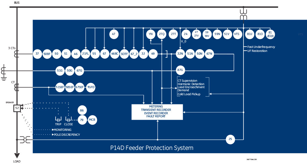
ANSI® Device Numbers and Functions
| Device Number | Function |
|---|---|
| 21BL | Load encroachment supervision (Load blinders) |
| 24 | Volts per Hertz |
| 25 | Check Synchronising |
| 27 | Phase and Line Undervoltage |
| 27V | Positive Suquence Undervoltage |
| 27Q | UV Reactive Power |
| 27T | Timed Undervoltage |
| 32 | Phase Directional Power |
| 32N | Wattmetric Ground Fault |
| 37 | Undercurrent |
| 46 | Negative Sequence Overcurrent |
| 47 | Negative Sequence Overvoltage |
| 49 | Thermal Overload |
| 50/27 | Switch-on to Fault |
| 50 | Phase Definitive Time Overcurrent |
| 51 | Phase Inverse-Time Overcurrent |
| Device Number | Function |
|---|---|
| 52 | Breaker and Isolator Control |
| 52PD | Pole Discrepancy |
| 55 | Power Factor |
| 59 | Phase and Line Overvoltage |
| 59V | Positive Sequence Overvoltage |
| 67 | Directional Phase Overcurrent |
| 68 | Inrush Blocking |
| 79 | Autoreclose |
| 86 | Latching/Lockout Contacts |
| 21FL | Fault Locator |
| 46BC | Broken Conductor |
| 50BF | CB Failure |
| 50N/G | Neutral/Ground Definitive Time Overcurrent |
| 51N/G | Neutral/Ground IDMT Overcurrent |
| SEF | Sensitive Earth Fault |
| 51R | Voltage Restrained Overcurrent |
| Device Number | Function |
|---|---|
| 51V | Voltage Controlled Overcurrent |
| 67_2 | Directional Negative Sequence Overcurrent |
| 59N | Neutral Voltage Displacement |
| 67N | Directional Neutral/Ground Overcurrent |
| 81df/dt | Rate of Change Frequency |
| 81O | Overfrequency |
| 81U | Underfrequency |
| 81V | Undervoltage Blocking |
| 87G | Restricted Ground Fault (REF) |
| CLP | Cold Load Pick Up |
| CTS/VTS | CT and VT Supervision |
| DC Supply Monitoring | |
| Fast underfrequency | |
| Underfrequency Restoration | |
| TGFD | Transient Ground Fault Detection |
| THD | Hamonic Measurement/Protection |
| YN | Neutral Admittance |
Advanced Communications
Three communication ports are standard: a rear serial port providing remote communications, a front USB port, and a rear Ethernet for device configuration and management.
Two additional Ethernet ports can be ordered to achieve Ethernet communication redundancy.
Supported Communication Protocols Include:
- Modbus (RS485 serial or Ethernet)
- IEC 60870-5-103
- DNP 3.0 (RS485 serial or Ethernet)
- IEC 61850 Ed. 2 with concurrent serial connection
- Redundant Ethernet protocols PRP, HSR, and failover also available with dual RJ45 or dual fiber media
Flexible Hardware
- Space-saving 4U height with 6" (30TE) case size
- Wide choice of opto-isolated binary inputs and output relays
- Binary inputs ESI 48-4 EB2 compliant – avoids spurious pickup from induction on field wiring
- High density I/Os in various combinations depending on case size option
- Ungrouped binary inputs for trip circuit supervision
- Field upgradeable, avoiding costly hardware changes
- 6" (30TE) models can accommodate:
- 1 x RS485/IRIG-B interface
- Up to 3 x RJ45/fiber optic ports for single and redundant Ethernet plus additional engineering access
- From 11 to 30 binary inputs, and 9 to 25 relay outputs, depending on the order code
Simulation & Testing
To aid commissioning, a simulation feature is provided to test the relay’s functionality and response to programmed conditions, without the need for external AC voltage and current inputs. When placed in simulation mode, the relay suspends reading actual AC inputs, generates samples to represent the programmed phasors, and loads these samples into the memory to be processed by the relay. Normal (pre-fault), fault, and post-fault conditions can be simulated to exercise a variety of relay features. Other test operations, such as an LED lamp testing for each color, contact input states, and testing of output relays, are also possible.
Application Model Selection
| Model | Hardware Base | Intended Application | Case Model |
|---|---|---|---|
| P14NB | P14N | Non-directional feeder | 30TE |
| P14NL | P14N | Non-directional feeder with autoreclose | 30TE |
| P14NZ | P14N | Non-directional feeder with autoreclose and HIF** downed conductor | 20TE/30TE |
| P14DB | P14D | Directional feeder | 30TE |
| P14DL | P14D | Advanced directional feeder with autoreclose and check synchronising | 30TE |
| P14DZ | P14D | Advanced directional feeder with TGFD transient ground fault detection | 30TE |
| P94VB | P94V | Voltage and frequency | 30TE |
| P94VP | P94V | Voltage and frequency with autoreclose and check synchronising | 30TE |
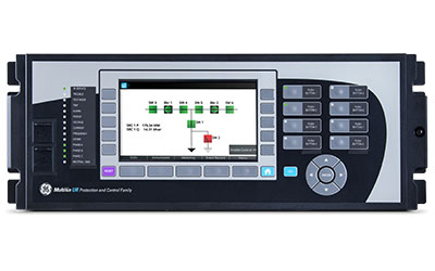
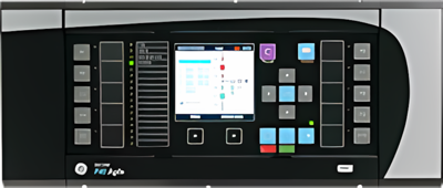
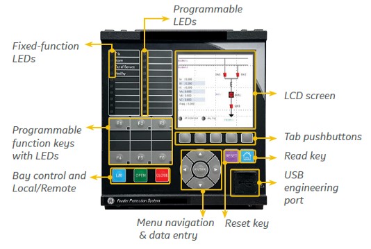 Multilin Agile front panel interface – ANSI version
Intuitive User interface.
The front HMI hosts a fully graphical color screen. The front panel supports open, close, local/remote, and direct function key access, facilitating the control of connected switchgear and managing up to six controllable devices. These replace traditional hardwired control scheme switches and annunciation, saving on engineering time and wiring costs.
Sixteen tricolor LED lamps are available and freely configurable, in addition to four fixed-function LEDs that provide a cost-effective solution for annunciation.
Multiple languages are supported with easy switching between English and an additional language on the local display without uploading new firmware.
A USB front port allows ready access by field personnel laptops.
Intuitive Graphical Display
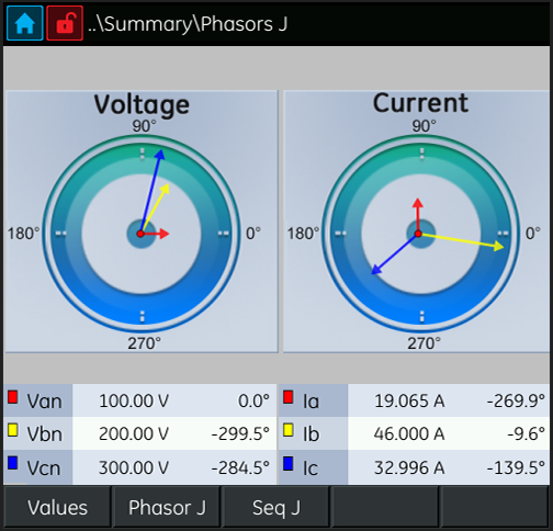
Phasor view for effective monitoring, commissioning & troubleshooting

Extensive recording for in-depth post-fault analysis
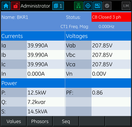
Accurate, real-time display of AC analog measurements
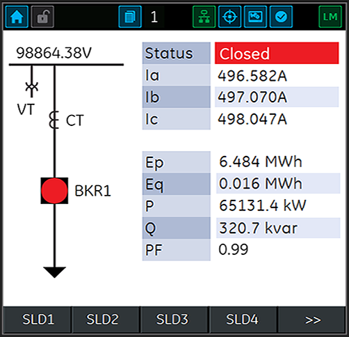
Enhanced bay visualization & control aided by single line diagram display
Product Explorer
Recommended Products & services
Multilin F650
The Multilin F650 has been designed for the protection, control and automation of feeders...
View More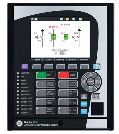
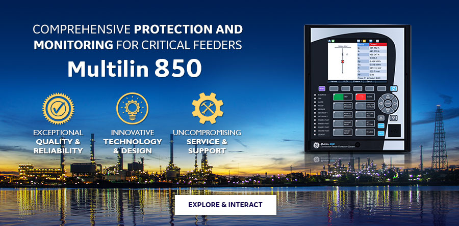
Multilin 850
The Multilin™ 850 relay is a member of the Multilin 8 Series protective relay...
View More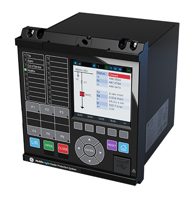
Multilin Agile
GE Vernova’s Multilin Agile Feeder Protection solution offers advanced protection,...
View MoreMultilin 850
Innovative feeder and bay controller in one box
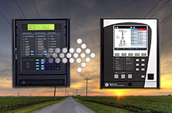
The Multilin™ 850 relay is a member of the Multilin 8 Series protective relay platform and has been designed for the management, protection and control of feeder applications. The Multilin 850 is an integrated, one box solution, used to provide comprehensive protection, control and monitoring of underground and overhead single or dual feeders in industrial and utility power networks.
Multilin 850
Innovative feeder and bay controller in one box
The Multilin™ 850 relay is a member of the Multilin 8 Series protective relay platform and has been designed for the management, protection and control of feeder applications. The Multilin 850 is an integrated, one box solution, used to provide comprehensive protection, control and monitoring of underground and overhead single or dual feeders in industrial and utility power networks.
Multilin 850 Overview
The Multilin 850 is an advanced feeder protection relay that provides high performance protection, high density I/O, extensive programmable logic and flexible configuration capabilities. With protection and control logic, the 850 allows for simplified coordination with upstream and downstream disconnect devices. The Multilin 850 supports both industrial and distribution utility feeders. Dual feeders (850D) and multi feeder (850P) in electrical applications are also supported.
As part of the 8 Series platform of relays, the Multilin 850 shares the advanced communications and cyber security features and EnerVista software suite that is common to the platform. Learn more about the Multilin 8 Series platform.
Comprehensive feeder protection
- One box solution with advanced logic and configuration flexibility to provide comprehensive primary or backup protection, control and monitoring for 2 feeders or for feeders with 2 sets of voltage inputs.
- breaker diagnostics with high-end fault and disturbance recording
- Integrated arc flash detection using light sensors supervised by overcurrent to reduce incident energy and equipment damage.
- High-end cyber security such as AAA, Radius, RBAC and Syslog, enabling NERC CIP requirements.
- Draw-out design simplifies testing, commissioning and maintenance, increasing process uptime.
- Optional Wi-Fi connectivity minimizes system configuration and provides safe relay programming and diagnostic retrieval.
- Patented environmental monitoring, providing visibility to changes in environmental conditions that can affect relay life.
Multilin 850 feeder protection relay functional block diagram
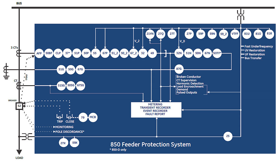
ANSI Device Numbers & Functions
| Device Number | Function |
|---|---|
| 21 YN | YN Neutral Admittance |
| 25 | Synchrocheck |
| 27P | Phase Undervoltage |
| 27Q | UV Reactive Power |
| 27T | Timed Undervoltage Protection |
| 27X | Auxiliary Undervoltage |
| 32 | Directional Power |
| 32N | Wattmetric Ground Fault (Wattmetric zero sequence directional) |
| 37 | Undercurrent |
| 49 | Thermal Overload |
| 50BF | Breaker Failure |
| 50G | Ground Instantaneous Overcurrent |
| 50SG | Sensitive Ground Instantaneous Overcurrent |
| 50N | Neutral Instantaneous Overcurrent |
| Device Number | Function |
|---|---|
| 50P | Phase Instantaneous Overcurrent |
| 50_2 | Negative Sequence Instantaneous Overcurrent |
| 51G | Ground Time Overcurrent |
| 51SG | Sensitive Ground Time Overcurrent |
| 51N | Neutral Time Overcurrent |
| 51P | Phase Time Overcurrent |
| 51_2 | Negative Sequence Time Overcurrent |
| 52 | AC Circuit Breaker |
| 55 | Power Factor |
| 59N | Neutral Overvoltage |
| 59P | Phase Overvoltage |
| 59X | Auxiliary Overvoltage |
| 59_2 | Negative Sequence Overvoltage |
| 67G | Ground Directional Element |
| Device Number | Function |
|---|---|
| 67SG | Sensitive Ground Directional Element |
| 67N | Neutral Directional Element |
| 67P | Phase Directional Element |
| 67_2 | Negative Sequence Directional Element |
| 79 | Automatic Recloser |
| 81O | Overfrequency |
| 81U | Underfrequency |
| 81R | Frequency Rate of Change |
| 87G | Restricted Ground Fault (RGF) |
| AFP | Arc Flash Protection |
| CLP | Cold Load Pickup |
| I1/12 | Broken Conductor |
| MCB | Manual Close Blocking |
| SOTF | Switch Onto Fault |
| VTFF | Voltage Transformer Fuse Failure |
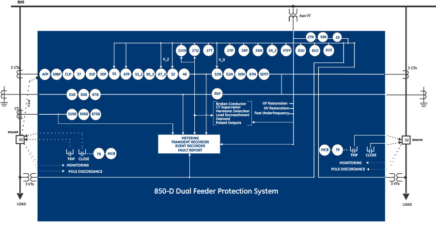
Dual Feeder Protection
The Multilin 850D is designed for high performance protection, control and monitoring of up to two distribution feeders, and provides all the functionalities required for a distribution feeder including SOFT, under current and pole discordance. Extensive programmable logic and flexible configuration capabilities along with sequence coordination enable the 850D to comply with system coordination requirements.
850D key features
- Up to 2 feeders within one relay
- Dual voltage banks with single feeder
- High-end cyber security such as AAA, Radius, RBAC, and Syslog helps enable NERC® CIP requirements
- Draw-out design simplifies testing, commissioning and maintenance, thereby increasing process uptime
- Wi-Fi connectivity minimizes system configuration and provides safe relay programming and diagnostic retrieval
- Relay environmental diagnostic information helps reduce system downtime
Multilin 850D functional block diagram
ANSI Device Numbers & Functions
|
|
| ||||||||||||||||||||||||||||||||||||||||||||||||||||||||||||||||||||||||||||||||||||||||||||||
* Only for 850D | ||||||||||||||||||||||||||||||||||||||||||||||||||||||||||||||||||||||||||||||||||||||||||||||||
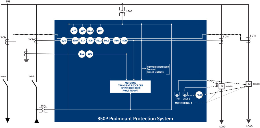
Multi Feeder Protection
Manufacturing for the 850P has been discontinued. As an alternative, please refer to the 850D
The Multilin 850P relay has been designed for the management, protection and control of multi feeder applications supporting both traditional voltage inputs as well as Low Energy Analog (LEA) inputs. A maximum of 4 feeders can be supported by the 850P.
The 850P addresses the following customer challenges:
|
|
Key benefits
- Reduce number of IEDs in the system, resulting in lower capital and O&M costs, and smaller battery sizing
- Mean time to repair less than 15mins with field swappable PSU, draw out construction and ready to consume service reports
- Extend asset life with built-in environmental monitoring, battery and advanced breaker monitoring
- Same device-based solution (850D/P) reduces training needs, standardizes SKUs and harmonizes the user and operational experience
Multilin 850P functional block diagram
ANSI Device Numbers & Functions
|
|
| ||||||||||||||||||||||||||||||||
Note: Ground option is not available for 4 sets of phase protection. | ||||||||||||||||||||||||||||||||||
 Fast, reliable arc flash protection with light-based arc flash sensors integrated within the Multilin 8 Series of protection & control devices. With arc flash detection in as fast as 2msec, the costs associated with equipment damage and unplanned down
Monitoring & Diagnostics
The Multilin 850 includes high accuracy metering and recording for all AC signals. Voltage, current, and power metering are built into the relay as a standard feature. Current and voltage parameters are available as total RMS magnitude, and as fundamental frequency magnitude and angle.
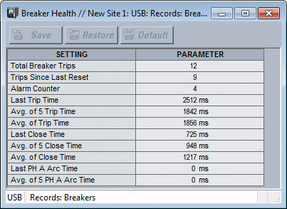
Breaker Health Monitoring
The breaker is monitored by the relay not only for detection of breaker failure, but also for the overall “breaker health” which includes:
- Breaker close and breaker open times
- Trip circuit monitoring
- Spring charging time
- Per-phase arcing current
- Trip counters
Data Logging
The Multilin 850 delivers comprehensive data logging providing the recording of 16 analog values selected from any analog values calculated by the relay. This data capture flexibility allows the operator to measure power factor or reactive power flow (for example), for several hours or even days, enabling detailed analysis and corrective action to be taken.
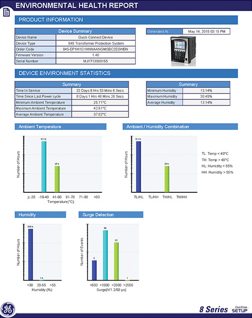
Environmental Monitoring
The 8 Series built-in environmental awareness feature (patent “Systems and methods for predicting maintenance of intelligent electronic devices”) collects the histograms of each operating condition from the point the device is put into service. Monitored environmental conditions include temperature, humidity and transient voltage. These parameters are now available as FlexElement to output alarms in case of limits reached due to Temperature, humidity or surges.
Trip and Close Circuit Monitoring
The 850 relay provides Trip and Close Circuit Monitoring elements
Breaker Arcing Current
This element calculates an estimate of the per-phase wear on the breaker contacts by measuring and integrating the current squared passing through the breaker contacts as an arc. When the threshold is exceeded in any phase, the relay can set an output operand and set an alarm.
Monitoring & Diagnostics
The Multilin 850 includes high accuracy metering and recording for all AC signals. Voltage, current, and power metering are built into the relay as a standard feature. Current and voltage parameters are available as total RMS magnitude, and as fundamental frequency magnitude and angle.
Breaker Health Monitoring
The breaker is monitored by the relay not only for detection of breaker failure, but also for the overall “breaker health” which includes:
- Breaker close and breaker open times
- Trip circuit monitoring
- Spring charging time
- Per-phase arcing current
- Trip counters
Data Logging
The Multilin 850 delivers comprehensive data logging providing the recording of 16 analog values selected from any analog values calculated by the relay. This data capture flexibility allows the operator to measure power factor or reactive power flow (for example), for several hours or even days, enabling detailed analysis and corrective action to be taken.
Environmental Monitoring
The 8 Series built-in environmental awareness feature (patent “Systems and methods for predicting maintenance of intelligent electronic devices”) collects the histograms of each operating condition from the point the device is put into service. Monitored environmental conditions include temperature, humidity and transient voltage. These parameters are now available as FlexElement to output alarms in case of limits reached due to Temperature, humidity or surges.
Trip and Close Circuit Monitoring
The 850 relay provides Trip and Close Circuit Monitoring elements
Breaker Arcing Current
This element calculates an estimate of the per-phase wear on the breaker contacts by measuring and integrating the current squared passing through the breaker contacts as an arc. When the threshold is exceeded in any phase, the relay can set an output operand and set an alarm.
8 Series Retrofit Kit
 Explore the 8 Series Retrofit Kit
Retrofit Existing SR 735 or SR 750/760 Devices to the Multilin 850 in Minutes
Traditionally, retrofitting an existing relay has been a challenging, time consuming task often requiring re-engineering, new drawings, panel modifications, re-wiring and re-testing.
The 8 Series Retrofit Kit provides a quick, 3-step solution to upgrade previously installed SR 735 or SR 750/760 Devices. With the new 8 Series Retrofit Kit users are able to install the 850 Feeder Management System without modifying existing cutouts and wiring, and without any drawing changes or re-engineering.
Buy 750/760 to 850 Retrofit Kit![]()
Easy 3-Step Process to Upgrade in as Fast as 21 Minutes
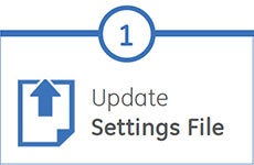
EnerVista 8 Series Setup Software provides automated setting file conversion. Once completed, a graphical report is provided to verify and call out any settings that need attention.
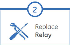
Simply remove the terminal blocks and then remove the SR chassis from the panel. No need to disconnect any of the field wiring.
Insert the new 8 Series Retrofit chassis into the switchgear and simply plug-in the old terminal blocks - there is no need to make any cut-out modifications or push and pull cables.
Recommended Products & services
Multilin F650
The Multilin F650 has been designed for the protection, control and automation of feeders...
View More
Multilin 850
The Multilin™ 850 relay is a member of the Multilin 8 Series protective relay...
View More
Multilin Agile
GE Vernova’s Multilin Agile Feeder Protection solution offers advanced protection,...
View MoreMultilin F35
Feeder Protection System
The F35, a member of the UR Family of protection relays, provides cost-effective feeder protection, control and metering for up to five feeders with busbar voltage measurement, or six feeders without busbar voltage in one integrated package. Use the F35 as a stand-alone device or as a component of an automated substation control system.
Multilin F35
Feeder Protection System
The F35, a member of the UR Family of protection relays, provides cost-effective feeder protection, control and metering for up to five feeders with busbar voltage measurement, or six feeders without busbar voltage in one integrated package. Use the F35 as a stand-alone device or as a component of an automated substation control system.

New and Enhanced Communication Capabilities
- New process bus module supports IEC 61869 sample values, PTP master capabilities and SV switching (FW 7.9x)
- New UR process bus modules supporting IEC61850-9-2LE Merging Units (FW 7.8x) Module Training available here
- Support switchable IEC 61850 Ed. 1 and Ed. 2 and redundant SNTP (FW 7.7x)
- New UR front panel with integrated 7” color, graphical display - providing operators with enhanced situational awareness (FW 7.6x)
- High density I/O module supporting up to 120 inputs or up to 72 contact outputs – eliminating the need for additional discrete devices (FW 7.6x)

Cyber Security - CyberSentry UR (FW v7.xx)
CyberSentryTM enables UR devices to deliver full cyber security features that help customers to comply with cyber security requirements (NERC CIP, IEEE 1686, IEC 62443, etc):
- Secured firmware upgrade: FW file includes hash code that enables authentication prior to being used for upgrading UR Relay (FW 7.9x)

Fully Compatible with IEC 61850-9-2LE or IEC61869 process bus schemes:
- Can connect to up to 8 merging units over -9-2LE or 61869
- Supports PRP, HSR, dual HSR and point-to-point process bus topology
- Provides support for GE Vernova’s IEC 61850 HardFiber Process Bus Solution

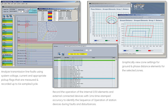
Extended Oscillography Records (FW v7.xx)
- Increased number of digital and analog channels (FW 7.90)
- Supports IEEE C37.111-1999/2013, IEC 60255-24 Ed 2.0 COMTRADE 2013 standard (FW v7.40)
- Configurable events allow for records of up to 45s at 64 samples per cycle

New and Enhanced Protection and Control Functionality
- New TGFD and Inrush detection elements (FW 8.0)
- Expanded Bay Controller Capabilities – providing a one box solution (FW 7.6x)
Key Features
- Instantaneous and time phase overcurrent protection
- Thermal overload, instantaneous and time ground/neutral overcurrent protection, wattmetric ground fault directional
- Transient ground fault detection (TGFD)
- Dedicated harmonic inrush detection
- Neutral and auxiliary overvoltage
- Phase and auxiliary undervoltage
- Underfrequency
- Four-shot automatic reclosers for up to six breakers
- Built-in selector switch
Protection & Control
The F35 feeder protection system provides feeder protection, control, monitoring and metering in an integrated, economical, and compact package. As part of the Universal Relay (UR) Family, the F35 provides cost-effective solutions and features high performance protection, expandable I/O options, integrated monitoring and metering, high-speed communications, and extensive programming and configuration capabilities. The F35 can be configured to protect up to six feeders or protect up to five feeders when bus voltage measurement is required. It also provides fast and deterministic execution of programmable logic necessary for substation automation applications. Graphical programming tools (Viewpoint Engineer), supported by a library of logic components, make the F35 simple to use and configure.
A sensitive wattmetric zero-sequence directional function can be used on isolated or resonant (Petersen coil) grounded, low-resistance grounded and solidly grounded systems to detect ground faults. This function determines the presence and direction of ground faults by measuring the value and direction of zero-sequence power. This flexible element responds to power derived from zero-sequence voltage and current in a direction specified by the element characteristic angle. Power can be selected as active, reactive, or apparent. Therefore, the element may be used to sense either forward or reverse ground.
The F35 has a wide range of protection elements that have many years of proven field experience.
Functional Block Diagram
ANSI® Device Numbers & Functions
| Device Number | Function |
|---|---|
| 27P | Phase Undervoltage |
| 27X | Auxiliary Undervoltage |
| 32N | Wattmettric Zero-Sequence Directional |
| 49 | Thermal overload protection |
| 50DD | Disturbance detector |
| 50G | Ground Instantaneous Overcurrent |
| 50N | Neutral Instantaneous Overcurrent |
| Device Number | Function |
|---|---|
| 50P | Phase Instantaneous Overcurrent |
| 50_2 | Negative Sequence Instantaneous Overcurrent |
| 51G | Ground Time Overcurrent |
| 51N | Neutral Time Overcurrent |
| 51P | Phase Time Overcurrent |
| 51_2 | Negative-sequence time overcurrent |
| 52 | AC circuit breaker |
| Device Number | Function |
|---|---|
| 59N | Neutral Overvoltage |
| 59P | Phase overvoltage |
| 59X | Auxiliary Overvoltage |
| 79 | Automatic Recloser |
| 81U | Under Frequency |
| TGFD | Transient ground fault detection |
| TGFD | Harmonic/Inrush detection |
Key Features
- Metering - current, voltage, power, energy, frequency and harmonics
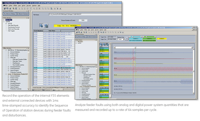
- Oscillography – analog and digital parameters at 64 samples/cycle
- Event Recorder - 1024 time tagged events with 0.5ms scan of digital inputs
- Data Logger - 16 channels with sampling rate up to 1 sample / cycle
- Setting for security audit trails for tracking changes to F35 configurations
Monitoring & Diagnostics
The F35 includes high accuracy metering and recording for all AC signals. Voltage, current, and power metering are built into the relay as a standard feature. Current and voltage parameters are available as total RMS magnitude, and as fundamental frequency magnitude and angle.
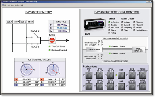
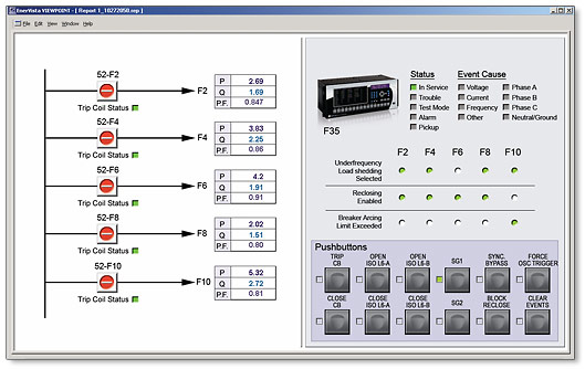 The F35 is the single point for protection, control, metering, and monitoring in one integrated device that can easily be connected directly into DCS or SCADA monitoring and control systems like Viewpoint Monitoring as shown.
Advanced Automation
The F35 incorporates advanced automation features including powerful FlexLogic™ programmable logic, communication, and SCADA capabilities that far surpass what is found in the average line relay. The F35 integrates seamlessly with other UR relays for complete system protection, including unit and auxiliary transformers, and balance of plant protection.
 The F35 is the single point for protection, control, metering, and monitoring in one integrated device that can easily be connected directly into DCS or SCADA monitoring and control systems like Viewpoint Monitoring as shown.
Key Features
Complete IEC 61850 Process Bus solution providing resource optimization and minimizing total P & C life cycle costs
- Three independent 100Mbps Ethernet ports enable purpose specific LAN support that eliminates latency effect of heavy traffic protocols on mission critical communication services
- Embedded IEEE 1588 time-synch protocol support eliminates dedicated IRIG-B wiring requirements for IEDs
- Direct I/O secures high-speed exchange of binary data between URs
- Increase network availability by reducing failover time to zero through IEC62439-3 PRP, HSR or dual HSR support
Advanced Communications
The F35 provides advanced communications technologies for remote data and engineering access, making it the easiest and most flexible feeder protection relay to use and integrate into new and existing infrastructures. Direct support for fiber optic Ethernet provides high-bandwidth communications allowing for low-latency controls and high-speed file transfers of relay fault and event record information. The available three independent and redundant Ethernet options provide the means to create fault tolerant communication architectures in an easy, cost-effective manner.
The F35 supports the most popular industry standard protocols enabling easy, direct integration into DCS and SCADA systems.
- IEC 61850-9-2LE networked or IEC61850-9-2 Hardfiber process bus support
- DNP 3.0 (serial & TCP/IP)
- Ethernet Global Data (EGD)
- IEC 60870-5-103 and IEC 60870-5-104
- Modbus RTU, Modbus TCP/IP
- HTTP, TFTP, SFTP and MMS file transfer
- Redundant SNTP and IEEE 1588 for time synchronization
- PRP as per IEC 62439-3
- Supports Routable GOOSE (R-GOOSE)
Interoperability with Enbedded IEC 61850
Use the F35 with integrated IEC 61850 to lower costs associated with multi-feeder protection, control and automation. GE Vernova’s leadership in IEC 61850 comes from thousands of installed devices and follows on years of development experience with UCA 2.0.
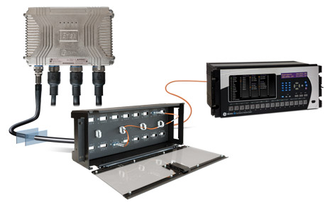
The F35’s IEC 61850 Process Bus module is designed to interface with the Multilin HardFiber System, allowing bi-directional IEC 61850 fiber optic communications. The HardFiber System is designed to integrate seamlessly with existing Universal Relay applications, including protection functions, FlexLogic, metering and communications.
Learn More![]()
The F35 can also connect to GE Vernova MU320 or third-party merging units using standard IEC 61869 or IEC 61850-9-2LE communication protocols.
Cyber Security - CyberSentry™ UR (FW v7.4xx)
CyberSentry enables UR devices to deliver full cyber security features that help customers to comply with NERC CIP and NITIR 7628 cyber security requirements through supporting the following core features:
Secure FW upgrade
UR FW files v7.9 and up now include a hash code that allows for authentication prior to being used for upgrading UR devices.
Password Complexity
Supporting up to 20 alpha- numeric or special characters, UR passwords exceed NERC CIP requirements for password complexity. Individual passwords per role are available.
AAA Server Support (Radius)
Enables integration with centrally managed authentication and accounting of all user activities and uses modern industry best practices and standards that meet and exceed NERC CIP requirements for authentication and password management.
Role Based Access Control (RBAC)
Efficiently administrate users and roles within UR devices. The new and advanced access functions allow users to configure up to five roles for up to eight configurable users with independent passwords. The standard “Remote Authentication Dial In User Service” (Radius) is used for authentication.
Event Recorder (Syslog for SEM)
Capture all cyber security related events within a SOE element (login, logout, invalid password attempts, remote/local access, user in session, settings change, FW update, etc), and then serve and classify data by security level using standard Syslog data format. This enables UR devices integration with established SEM (Security Event Management) systems.
EnerVista™ Software
The EnerVista™ suite is an industry-leading set of software programs that simplifies every aspect of using the F35 relay. The EnerVista™ suite provides all the tools to monitor the status of the protected asset, maintain the relay, and integrate information measured by the F35 into DCS or SCADA monitoring systems. Convenient COMTRADE and Sequence of Events viewers are an integral part of the UR setup software included with every UR relay, to carry out postmortem event analysis and ensure proper protection system operation.
Learn More![]()
Multilin F60
Feeder Protection System
The F60, a member of the UR Family of protection relays, provides high performance feeder protection, control, monitoring and metering in an integrated, economical, and compact package. The F60 includes GE Vernova Multilin’s unique high-impedance fault detection for fast and reliable detection of downed conductors.
New and Enhanced Communication Capabilities
- New process bus module supports IEC 61869 sample values, PTP master capabilities and SV switching (FW 7.9x)
- New UR process bus modules supporting IEC61850-9-2LE Merging Units (FW 7.8x) Module Training available here
- Support switchable IEC 61850 Ed. 1 and Ed. 2 and redundant SNTP (FW 7.7x)
- New UR front panel with integrated 7” color, graphical display - providing operators with enhanced situational awareness (FW 7.6x)
- High density I/O module supporting up to 120 inputs or up to 72 contact outputs – eliminating the need for additional discrete devices (FW 7.6x)
Cyber Security - CyberSentry UR (FW v7.xx)
CyberSentryTM enables UR devices to deliver full cyber security features that help customers to comply with cyber security requirements (NERC CIP, IEEE 1686, IEC 62443, etc):
- Secured firmware upgrade: FW file includes hash code that enables authentication prior to being used for upgrading UR Relay (FW 7.9x)
Fully Compatible with IEC 61850-9-2LE or IEC61869 process bus schemes:
- Can connect to up to 8 merging units over -9-2LE or 61869
- Supports PRP, HSR, dual HSR and point-to-point process bus topology
- Provides support for GE Vernova’s IEC 61850 HardFiber Process Bus Solution
Extended Oscillography Records (FW v7.xx)
- Increased number of digital and analog channels (FW 7.90)
- Supports IEEE C37.111-1999/2013, IEC 60255-24 Ed 2.0 COMTRADE 2013 standard (FW v7.40)
- Configurable events allow for records of up to 45s at 64 samples per cycle
New and Enhanced Protection and Control Functionality
- New TGFD and Inrush detection elements (FW 8.0)
- Expanded Bay Controller Capabilities – providing a one box solution (FW 7.6x)
Key Features
- High-impedance fault detection (downed conductor detection)
- Multiple phase, ground, neutral and negative sequence instantaneous and timed overcurrent elements
- Phase and negative sequence directional overcurrent, Neutral directional with enhanced polarity criteria, broken conductor and thermal overload
- Load encroachment supervision
- Wattmetric ground fault detection
- Transient ground fault detection (TGFD)
- Incipient cable fault detection
- Four-shot autorecloser with synchronism check
- Breaker control and breaker failure
- Abnormal frequency protection (rate of change, under and over frequency)
- Restricted Ground Fault (RGF)
- Dedicated harmonic/inrush detection
Protection & Control
The F60 feeder protection system provides feeder protection, control, monitoring and metering in an integrated, economical, and compact package. As part of the Universal Relay (UR) Family, the F60 features high performance protection, expandable I/O options, integrated monitoring and metering, high-speed communications, and extensive programming and configuration capabilities. The F60 incorporates a unique and matured algorithm to detect high-impedance faults such as downed conductor detection. It also provides fast and deterministic execution of programmable logic necessary for substation automation applications. Graphical programming tools (Viewpoint Engineer), supported by a library of logic components, make the F60 simple to use and configure. The F60 has a wide range of protection elements that have many years of proven field experience.
Functional Block Diagram
ANSI® Device Numbers & Functions
|
|
|
Key Features
- Metering - current, voltage, power, energy, frequency
- Oscillography – analog and digital parameters at 64 samples/cycle
- Event Recorder - 1024 time tagged events with 0.5ms scan of digital inputs
- Data Logger - 16 channels with sampling rate up to 1 sample / cycle
- Setting for security audit trails for tracking changes to D30 configurations
Monitoring & Diagnostics
 The D30 is the single point for protection, control, metering, and monitoring in one integrated device that can be easily connected directly to HMI or SCADA monitoring and control systems.
Advanced Automation
The D30 incorporates advanced automation features including powerful FlexLogic™ programmable logic, communication, and SCADA capabilities that far surpass what is found in the average line protection relay used for subtransmission. The D30 integrates seamlessly with other UR relays for complete system protection.
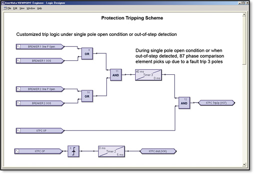 FlexLogic™ allows for the customization of D30 for custom protection, control and automation, allowing users to build line protection schemes and applications for their equipment.
Key Features
Complete IEC 61850 Process Bus solution providing resource optimization and minimizing total P & C life cycle costs
- Three independent 100Mbps Ethernet ports enable purpose specific LAN support that eliminates latency effect of heavy traffic protocols on mission critical communication services
- Embedded IEEE 1588 time-synch protocol support eliminates dedicated IRIG-B wiring requirements for IEDs
- Direct I/O secures high-speed exchange of binary data between URs
- Increase network availability by reducing failover time to zero through IEC62439-3 PRP, HSR or dual HSR support
Advanced Communications
The F60 provides advanced communications technologies for remote data and engineering access, making it easy and flexible to use and integrate into new and existing infrastructures. Direct support for fiber optic Ethernet provides high-bandwidth communications allowing for low-latency controls and high-speed file transfers of relay fault and event record information. The available three independent and redundant Ethernet options provide the means to create fault tolerant communication architectures in an easy, cost-effective manner.
The F60 supports the most popular industry standard protocols enabling easy, direct integration into monitoring and SCADA systems.
- IEC 61850-9-2LE/IEC 61869 networked or IEC61850-9-2 Hardfiber process bus support
- DNP 3.0 (serial & TCP/IP)
- IEC 60870-5-103 and IEC 60870-5-104
- Modbus RTU, Modbus TCP/IP
- HTTP, TFTP, SFTP and MMS file transfer
- Redundant SNTP and IEEE 1588 for time synchronization
- PRP as per IEC 62439-3
- Supports Routable GOOSE (R-GOOSE)
Interoperability with Embedded IEC 61850
Use the F60 with integrated IEC 61850 to lower costs associated with feeder protection, control and automation. GE Vernova’s leadership in IEC 61850 comes from thousands of installed devices and follows on years of development experience with UCA 2.0.
The F60’s IEC 61850 Process Bus module is designed to interface with the Multilin HardFiber System, allowing bi-directional IEC 61850 fiber optic communications. The HardFiber System is designed to integrate seamlessly with existing Universal Relay applications, including protection functions, FlexLogic, metering and communications.
The F60 can also connect to GE Vernova MU320 or third-party merging units using standard IEC 61869 or IEC 61850-9-2LE communication protocols.
Cyber Security - CyberSentry™ UR (FW v7.4xx)
CyberSentry enables UR devices to deliver full cyber security features that help customers to comply with NERC CIP and NITIR 7628 cyber security requirements through supporting the following core features:
Secure FW upgrade
UR FW files v7.9 and up now include a hash code that allows for authentication prior to being used for upgrading UR devices.
Password Complexity
Supporting up to 20 alpha- numeric or special characters, UR passwords exceed NERC CIP requirements for password complexity. Individual passwords per role are available.
AAA Server Support (Radius)
Enables integration with centrally managed authentication and accounting of all user activities and uses modern industry best practices and standards that meet and exceed NERC CIP requirements for authentication and password management.
Role Based Access Control (RBAC)
Efficiently administrate users and roles within UR devices. The new and advanced access functions allow users to configure up to five roles for up to eight configurable users with independent passwords. The standard “Remote Authentication Dial In User Service” (Radius) is used for authentication.
Event Recorder (Syslog for SEM)
Capture all cyber security related events within a SOE element (login, logout, invalid password attempts, remote/local access, user in session, settings change, FW update, etc), and then serve and classify data by security level using standard Syslog data format. This enables UR devices integration with established SEM (Security Event Management) systems.
EnerVista™ Software
The EnerVista™ suite is an industry-leading set of software programs that simplifies every aspect of using the F60 relay. The EnerVista™ suite provides all the tools to monitor the status of the protected asset, maintain the relay, and integrate information measured by the F60 into DCS or SCADA monitoring systems. Convenient COMTRADE and Sequence of Events viewers are an integral part of the UR setup software included with every UR relay, to carry out postmortem event analysis and ensure proper protection system operation.
Recommended Products & services
P84 MiCOM 5th Generation
The P84, part of the MiCOM P40 Agile 5th Generation family, is a multi-functional line...
View More
Multilin F60
The F60, a member of the UR Family of protection relays, provides high performance feeder...
View More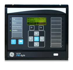
MiCOM Agile P140 Series
Part of the MiCOM P40 platform, the Agile P14x feeder management relays provide an...
View MoreP84 MiCOM 5th Generation
Multi-Functional Line Terminal Protection
The P84, part of the MiCOM P40 Agile 5th Generation family, is a multi-functional line terminal Protection that delivers high performance processing and a graphical HMI as standard. It is ideal for HV, EHV and UHV applications on lines and cables for 1 or 2 breaker applications with patented adaptive auto-reclose functionality.
P84 MiCOM 5th Generation
Multi-Functional Line Terminal Protection
The P84, part of the MiCOM P40 Agile 5th Generation family, is a multi-functional line terminal Protection that delivers high performance processing and a graphical HMI as standard. It is ideal for HV, EHV and UHV applications on lines and cables for 1 or 2 breaker applications with patented adaptive auto-reclose functionality.
What's New
Overview
Transmission and distribution systems are essential for the safe, sure routing of power from generation sources to consumers. However, exposed overhead lines transporting power are by nature sometimes vulnerable and prone to fault. In the case of a faulty circuit, the MiCOM range provides speedy protection to trip and isolate it, thereby preventing further damage. Each relay model contains a complete suite of backup protection elements covering all current, voltage and frequency applications. This permits simplified application and spares holdings, because the relay can be adopted as the standard protection platform.
The MiCOM P84 is suitable for feeders controlled by a single circuit breaker and for complex installations where feeders are controlled by two circuit breakers such as ring bus/mesh corner formations and the breaker-and-a-half configurations.
Key Benefits
- Extremely versatile, e.g. managing leader-follower reclosing schemes in the event of dual breaker application
- Multi-shot 1/3pole & 3pole autoreclosure with check synchronism - adaptive technology to detect fault arc extinction and accelerate the dead time or drive to lockout for persistent faults. Improves system stability whilst reducing OPEX.
- Fast CB failure resetting (<3/4 cycle).
- Same heritage as the class leading MiCOMho P44 and MiCOM P54 family of products.
Main characteristics:
- Comprehensive communication options including IEC 61850 Edition 2
- IEC 61850 redundant Ethernet protocols - RSTP, PRP or HSR
- IEC 61850 9-2LE redundant PRP Process bus protocol
- Advanced Cybersecurity including AAA, Radius, RBAC, and Syslog
P84 MiCOM 5th Generation
MiCOM Multi-Functional Line Terminal Protection
Buy Now![]()
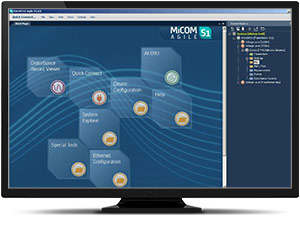
MiCOM S1 Agile
Key benefits:
- Powerful, free of charge, PC toolsuite
- Optimum management of the installed base, structured as per the substation topology
- Intuitive and versatile interface with file management facilities
- Logical structure based on substation, voltage level and bay
- Version control and cross-checking facilities for IED settings
- Real-time measurement visualization – MiCOM S1 Agile extends to all MiCOM Agile IEDs - including P847 PMU and busbar schemes
Engineering Tool Suite
S1 Agile is the truly universal PC tool for MiCOM Agile relay, assemble all tools in a palette for simple entry, with intuitive navigation via fewer mouse-clicks. No-longer are separate tools required for redundant Ethernet configuration, phasor measurement unit commissioning, busbar scheme operational dashboards, programmable curve profiles or automatic disturbance record extraction – applications are embedded. MiCOM S1 Agile supports all existing MiCOM, K-Series and Modulex, including a utility for automatic conversion of setting files from previous generations of numerical relays like K-series and MiCOM P20 to the latest P40 Agile models.
To move to the future, with no loss of functionality, no loss of device support, and full compatibility with your installed base and system architecture – request a copy of S1 Agile with the contact form link below.
Key features in the MiCOM S1 family:
- GE Vernova’s integrated engineering tool that provides users with access to automation IED configuration and record data
- Integrated configuration and monitoring features
- Send and extract setting files
- Single Line Diagram creation with inbuilt editor
- Event and disturbance record extraction and analysis
MiCOM S1 Agile software request
To receive the MiCOM S1 Agile, please use our Contact form. This will also ensure that you are kept up-to-date with the latest enhancements, including updates and bug fixes.
Refurbishment Solutions
GE Vernova’s latest P84 MiCOM 5th Generation transmission models offer a perfect functional match to our “mho” family of distance relays, from the heritage installed-base brands GE VERNOVA and Areva. The protection pedigree is maintained, optimised and advanced:
MiCOM P841A/B Relay Replacement:
- Form, fit and functional compatibility – the P84 fits in the same panel or rack space and offers the same features and Protection performance.
- The same S1 Agile software supports the new MiCOM relay and the legacy P841A/B
Pin-Pin Upgrade Methodology:
- Take the order code (CORTEC) of the older relay being removed, typically a blue case relay
- Translate to today’s latest GE Vernova MiCOM model, adding Ethernet options if required
- Order the new P40 relay
- Extract settings and logic, use S1 Agile toolsuite to convert settings
- Detach the terminal blocks from old relay, leaving wiring attached / detach terminal blocks from the new.
- Carefully examine the terminal blocks to see that no physical damage has occurred since installation.
- Mount new relay. Old relay blocks fit straight onto the new relay - safer, less wiring to reconnect.
- It is recommended to apply rated current and voltage to the relay CT/VT inputs during secondary injection testing to check the continuity of the CT/VT terminal block connections to the relay.
- Download converted files
- Test, return circuit to service with only minutes of downtime
Recommended Products & services
P84 MiCOM 5th Generation
The P84, part of the MiCOM P40 Agile 5th Generation family, is a multi-functional line...
View More
Multilin F60
The F60, a member of the UR Family of protection relays, provides high performance feeder...
View More
MiCOM Agile P140 Series
Part of the MiCOM P40 platform, the Agile P14x feeder management relays provide an...
View MoreHID
High Impedance Differential Module
Use the HID module in conjunction with a high-speed overcurrent relay to provide three phase high impedance differential protection for substation busbars of any voltage level. Additionally, it can also be used to protect electrical machines like transformers, generators or motors against restricted ground faults.
Each HID module includes resistors that provide the associated high impedance relay with stability againstexternal faults, and varistors (MOV - Metal Oxide Varistors) in order to limit the secondary peak voltage below 2 kV during fault conditions.
HID
High Impedance Differential Module
Use the HID module in conjunction with a high-speed overcurrent relay to provide three phase high impedance differential protection for substation busbars of any voltage level. Additionally, it can also be used to protect electrical machines like transformers, generators or motors against restricted ground faults.
Each HID module includes resistors that provide the associated high impedance relay with stability againstexternal faults, and varistors (MOV - Metal Oxide Varistors) in order to limit the secondary peak voltage below 2 kV during fault conditions.
Recommended Products & services

Bus Protection
GE Vernova provides enhanced reliability through advanced protection for a wide range of...
View MoreMVTP
Buswire Supervision Relay
Used to ensure the integrity of busbars and restricted earth fault schemes, the MVTP monitoring device has a low AC burden and requires no external resistors.
Single and 3-phase for continuous buswire supervision
Available in single and 3-phase relays, the MVTP provides continuous supervision of the buswires in high impedance type busbar protection schemes. It also detects open-circuited buswires as well as open-circuited main current transformers.
MVTP
Buswire Supervision Relay
Used to ensure the integrity of busbars and restricted earth fault schemes, the MVTP monitoring device has a low AC burden and requires no external resistors.
Single and 3-phase for continuous buswire supervision
Available in single and 3-phase relays, the MVTP provides continuous supervision of the buswires in high impedance type busbar protection schemes. It also detects open-circuited buswires as well as open-circuited main current transformers.
MFAC
High Impedance Bus Differential Relay
MFAC relays provide high-speed differential protection for various types of power system plants including generators, reactors, busbars, motors and the individual windings of power transformers. MFAC relays are fast and reliable due to simple electromechanical construction and operate as a high impedance unit protection scheme with a wide range of setting.
MCAG
High Impedance Bus Differential Relay
MCAG relays provide high-speed differential protection for various types of power system plants Including generators, reactors, busbars, motors and the individual windings of power transformers. The relays provide current-calibrated busbar differential and have an attracted armature design with simple and robust construction.
MiCOM Agile P746
Centralized Busbar Differential Relay
The MiCOM Agile P746 provides complete protection for MV and HV busbar configurations with up to 2 zones plus a check zone, and up to 18 terminals. The MiCOM Agile P746 provides a centralized one box or three box architecture and is very simple to use. as it does not need to be deeply engineered and supports easy operation and maintenance of busbars.
What's New
Overview
- Typical operating time of 12 ms with high speed/high break contacts or 17 ms with standard contacts
- Phase segregated biased current differential high speed busbar protection
- Easy maintenance, operation and future expansion of the busbar supported
- Deploy in ring-bus/mesh corners, single busbars, sectionalized busbars, and one per bus in breaker and a half topologies
Key benefits:
- Use one box for schemes up to 6 feeders, and 3 boxes (one per phase) for larger schemes up to 18 terminals
- Interoperable with all classes of CT: IEEE, IEC, air-gapped, non-gapped, and CTs with moderate knee point voltage
- 10 integrated function keys, tri-color LEDs, and graphical programmable logic permit the creation of comprehensive schemes, tailored to your needs
- IEC 61850 redundant Ethernet with RSTP and IEC 62439 PRP and HSR – with HSR support for up to 50 nodes in a ring
Functional Block Diagram
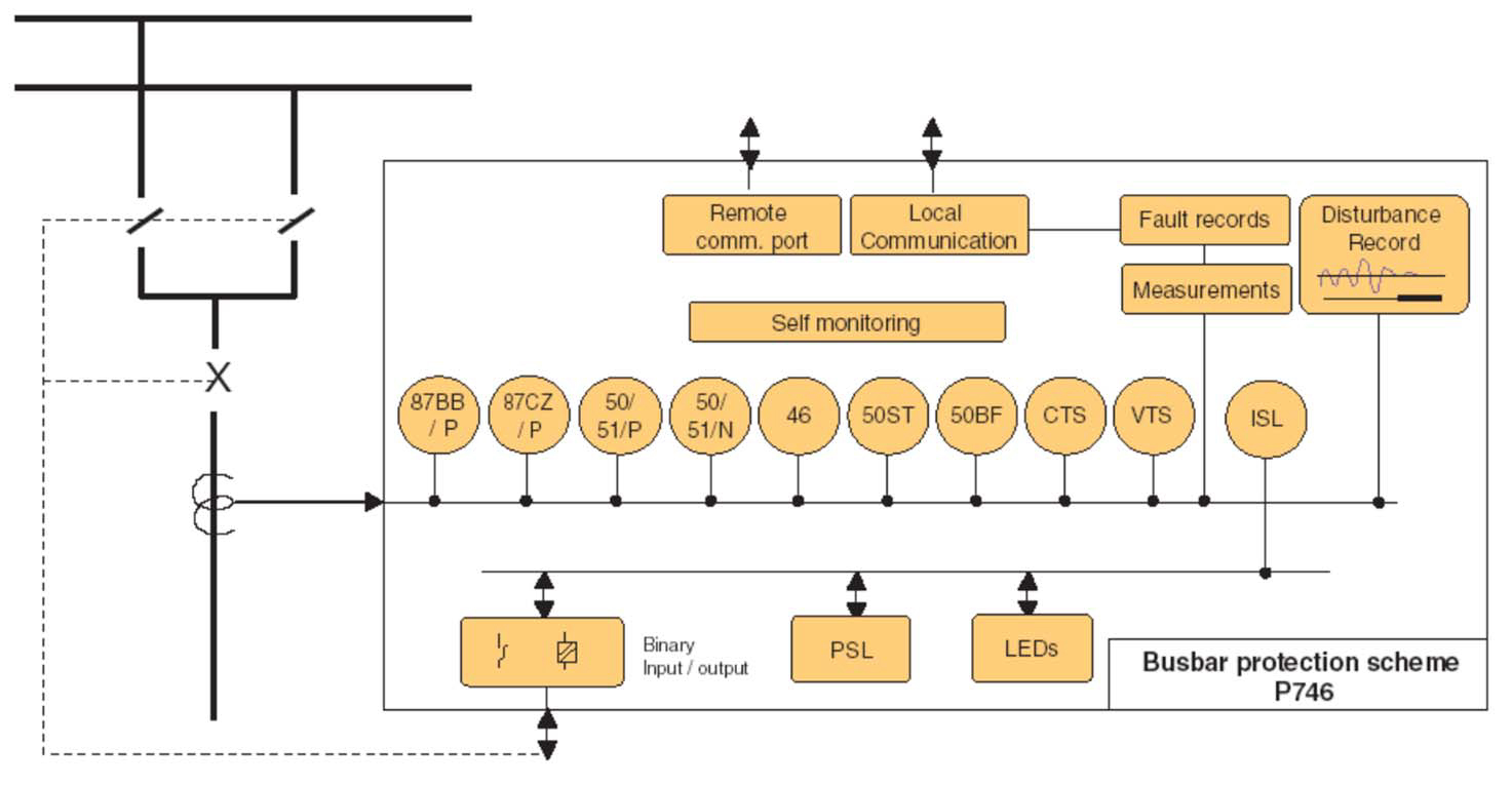
ANSI© Device Numbers and Functions
| Device Number | Function |
|---|---|
| 87BB | Bus Differential |
| 50 | Phase Definite Time Overcurrent |
| 51 | Phase Inverse-Time Overcurrent |
| 86 | Latching/Lockout Contacts |
| 50BF | CB Failure |
| 50N | Earth Fault Definite Time Overcurrent |
| 50ST | Short Zone Earth Fault |
| 51N | Neutral/Ground IDMT Overcurrent |
| VTS | VT Supervision |
| CTS | CT Supervision |
| PSL | Programmable Logic |
MiCOM S1 Agile
Key benefits:
- Powerful, free of charge, PC toolsuite
- Optimum management of the installed base, structured as per the substation topology
- Intuitive and versatile interface with file management facilities
- Logical structure based on substation, voltage level and bay
- Version control and cross-checking facilities for IED settings
- Real-time measurement visualization – MiCOM S1 Agile extends to all MiCOM Agile IEDs - including P847 PMU and busbar schemes
Engineering Tool Suite
S1 Agile is the truly universal PC tool for MiCOM Agile relay, assemble all tools in a palette for simple entry, with intuitive navigation via fewer mouse-clicks. No-longer are separate tools required for redundant Ethernet configuration, phasor measurement unit commissioning, busbar scheme operational dashboards, programmable curve profiles or automatic disturbance record extraction – applications are embedded. MiCOM S1 Agile supports all existing MiCOM, K-Series and Modulex, including a utility for automatic conversion of setting files from previous generations of numerical relays like K-series and MiCOM P20 to the latest P40 Agile models.
To move to the future, with no loss of functionality, no loss of device support, and full compatibility with your installed base and system architecture – request a copy of S1 Agile with the contact form link below.
Key features in the MiCOM S1 family:
- GE Vernova’s integrated engineering tool that provides users with access to automation IED configuration and record data
- Integrated configuration and monitoring features
- Send and extract setting files
- Event and disturbance record extraction and analysis
MiCOM S1 Agile software request
To receive the MiCOM S1 Agile, please use our Contact form. This will also ensure that you are kept up-to-date with the latest enhancements, including updates and bug fixes.
P746 Remote HMI PC Application Software
Agile P746 remote PC HMI provides the following features:
- P746 Remote HMI allows the user to display the MiCOM Agile P746 measured analogue quantities and DDB (digital data bus) status information dynamically via the user defined busbar topology
- Available in English, French, German, Spanish, Chinese and Russian
Please use our contact form to request the software.
Refurbishment Solutions
Refurbishment Solutions – “If It’s Blue Think to Renew”
GE Vernova’s latest MiCOM P746 model offers an ideal path to refurbish an older installed base of MiCOM P746 relays. Whether those older products were initially sold as GE VERNOVA or AREVA-branded products, newer models retain pin-pin refurbishment capability. Advantageously, users can benefit from the advancements made in protection, control, communications, hardware and cybersecurity that have taken place in the intervening years. The new P40 retains form, fit and function compatibility but delivers the latest platform and software ready for today’s environment, and for future-proofed application for the decades ahead.
Pin-Pin Upgrade Methodology:
- Take the order code (CORTEC) of the older relay being removed, typically a blue case relay
- Translate to today’s latest GE Vernova MiCOM model, adding Ethernet options if required
- Order the new P40 relay
- Extract settings and logic, use S1 Agile toolsuite to convert settings
- Detach the terminal blocks from old relay, leaving wiring attached / detach terminal blocks from the new.
- Carefully examine the terminal blocks to see that no physical damage has occurred since installation
- Mount new relay. Old relay blocks fit straight onto the new relay - safer, less wiring to reconnect.
- It is recommended to apply rated current and voltage to the relay CT/VT inputs during secondary injection testing to check the continuity of the CT/VT terminal block connections to the relay.
- Download converted files
- Test, return circuit to service with only minutes of downtime
Contact us for advice and support
Recommended Products & services
Multilin B90
The Multilin B90 bus protection relay, a member of the UR Family, features integrated...
View More
MiCOM Agile P746
The MiCOM Agile P746 provides complete protection for MV and HV busbar configurations...
View More
MiCOM Agile P747
The MiCOM Agile P747 provides complete protection for voltage levels up to extra high...
View More