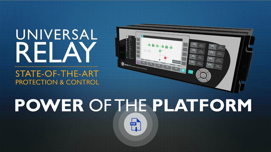
Multilin T60
Transformer Protection System
The T60 is designed for various power applications, including autotransformers, generator step-up transformers, split-phase, angle regulating transformers and reactors. It uses multiple current and voltage inputs to provide primary protection and backup protection of transformers, including differential, ground differential, five distance zones, phase, neutral, and ground overcurrent, under and overvoltage, under and overfrequency, over-fluxing, and breaker failure.

New and Enhanced Communication Capabilities
- New process bus module supports IEC 61869 sample values, PTP master capabilities and SV switching (FW 7.9x)
- New UR process bus modules supporting IEC61850-9-2LE Merging Units (FW 7.8x) Module Training available here
- Support switchable IEC 61850 Ed. 1 and Ed. 2 and redundant SNTP (FW 7.7x)
- New UR front panel with integrated 7” color, graphical display - providing operators with enhanced situational awareness (FW 7.6x)
- High density I/O module supporting up to 120 inputs or up to 72 contact outputs – eliminating the need for additional discrete devices (FW 7.6x)

Cyber Security - CyberSentry UR (FW v7.xx)
CyberSentryTM enables UR devices to deliver full cyber security features that help customers to comply with cyber security requirements (NERC CIP, IEEE 1686, IEC 62443, etc):
- Secured firmware upgrade: FW file includes hash code that enables authentication prior to being used for upgrading UR Relay (FW 7.9x)

Fully Compatible with IEC 61850-9-2LE or IEC61869 process bus schemes:
Can connect to up to 8 merging units over -9-2LE or 61869 Supports PRP, HSR, dual HSR and point-to-point process bus topology Provides support for GE Vernova’s IEC 61850 HardFiber Process Bus Solution

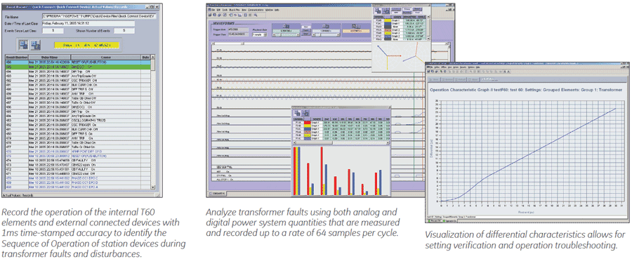
Extended Oscillography Records (FW v7.xx)
- Increased number of digital and analog channels (FW 7.90)
- Supports IEEE C37.111-1999/2013, IEC 60255-24 Ed 2.0 COMTRADE 2013 standard (FW v7.40)
- Configurable events allow for records of up to 45s at 64 samples per cycle

T60 Protection System to Deliver Synchrophasor Capabilities (FW version 5.90)

New and Enhanced Protection and Control Functionality
- Inter-turn transformer and dedicated Harmonic/Inrush detection elements (FW 8.0)
- • CT exclusion setting (FW 7.8)
- Expanded Bay Controller Capabilities – providing a one box solution (FW 7.6x)

New RRTD and RTD Alarm and Trip Settings
The T60 offers RTD alarm and trip settings to provide advanced monitoring of power transformers’ temperature. In addition, the RRTD module enables remote monitoring and metering of up to 12 programmable RTDs which reduces the number of RTD cables and provides temperature backup protection (firmware version 5.70). Learn More
Key Benefits
- Dual-slope, dual-breakpoint differential restraint characteristic, restrained and unrestrained differential, inter-turn fault detection
- 2nd harmonic inrush, overexcitation inhibit plus independent harmonic detection element
- Transformer overexcitation protection
- Restricted ground fault
- Loss-of-life, aging factor, hottest spot
- Five zones backup distance protection with power swing detection and load encroachment function
- Synchrocheck, ROCOF, over and under frequency
Protection & Control
The T60 transformer protection system is a comprehensive three-phase transformer relay designed to protect medium and large power transformers. The T60 provides automatic or user-definable magnitude reference winding selections for CT ratio matching, and performs automatic phase shift compensation for all types of transformer winding connections. The T60 algorithm allows the user to enable removal of the zero-sequence current even for delta-connected transformer windings, facilitating transformers with a variety of grounding configurations. As part of the Universal Relay (UR) Family, the T60 provides superior protection and control.
Functional Block Diagram
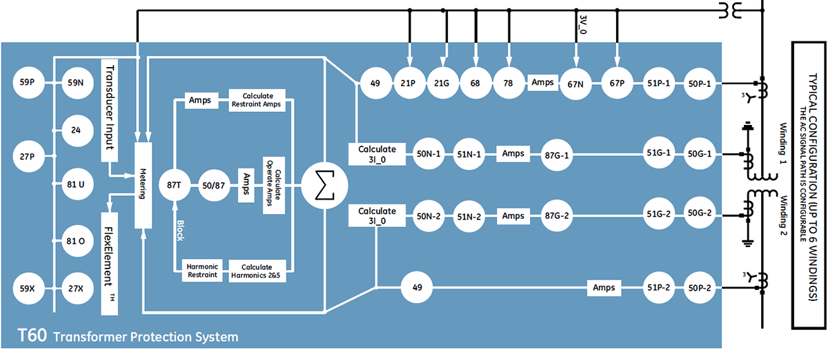
ANSI Device Numbers & Functions
| Device Number | Function |
|---|---|
| 21P | Phase Distance |
| 21G | Ground Distance |
| 24 | Volts Per Hertz |
| 25 | Synchrocheck |
| 27P | Phase Undervoltage |
| 27X | Auxiliary Undervoltage |
| 49 | Thermal Overload |
| 50BF | Breaker Failure |
| 50G | Ground Instantaneous Overcurrent |
| 50N | Neutral Instantaneous Overcurrent |
| Device Number | Function |
|---|---|
| 50P | Phase Instantaneous Overcurrent |
| 50/87 | Instantaneous Differential Overcurrent |
| 51G | Ground Time Overcurrent |
| 51N | Neutral Time Overcurrent |
| 51P | Phase Time Overcurrent |
| 59N | Neutral Overvoltage |
| 59P | Phase Overvoltage |
| 59X | Auxiliary Overvoltage |
| Device Number | Function |
|---|---|
| 67N | Neutral Directional Overcurrent |
| 67P | Phase Directional Overcurrent |
| 68 | Power Swing Blocking |
| 78 | Out-of-Step Tripping |
| 81O | Overfrequency |
| 81U | Underfrequency |
| 81R | Rate of Change of Frequency (ROCOF) |
| 87G | Restricted Ground Fault |
| 87T | Transformer Differential |
Key Features
- Metering - current, voltage, power, energy, frequency, temperature, transformer monitoring
- P & M class synchrophasors of voltage, current and sequence components – 1 to 120 frames/sec
- Oscillography – analog and digital parameters at 64 samples/cycle
- Event Recorder - 1024 time tagged events with 0.5ms scan of digital inputs
- Data Logger - 16 channels with sampling rate up to 1 sample / cycle
- Setting for security audit trails for tracking changes to T60 configurations
Monitoring & Diagnostic
The T60 includes high accuracy metering and recording for all AC signals. Voltage, current, and power metering are built into the relay as a standard feature. Current and voltage parameters are available as total RMS magnitude, and as fundamental frequency magnitude and angle. For power quality applcations, harmonic measurements (up to the 25th) for voltage and current are available. T60 can monitor, calculate and log hottest-spot temperature, aging factor and loss-of-life data over a long period. This data, combined with economic analysis, allows criteria to be developed regarding the best time at which to replace a power transformer due to load growth, i.e. to minimize the cost without significantly increasing the risk.
 The B30 is the single point for protection, control, metering, and monitoring in one integrated device that can easily be connected directly into DCS or SCADA monitoring and control systems like Viewpoint Monitoring.
Advanced Automation
The T60 incorporates advanced automation features including powerful FlexLogic™ programmable logic, communication, and SCADA capabilities that far surpass what is found in the average transformer relay. The T60 integrates seamlessly with other UR relays for complete system protection.
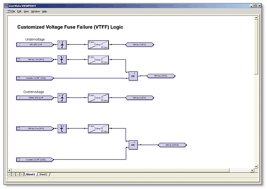 FlexLogic™ allows for the customization of the T60 to operate and control the breakers and other auxiliary devices needed to fit most generator protection schemes and applications.
Key Features
Complete IEC 61850 Process Bus solution providing resource optimization and minimizing total P & C life cycle costs
- Three independent 100Mbps Ethernet ports enable purpose specific LAN support that eliminates latency effect of heavy traffic protocols on mission critical communication services
- Embedded IEEE 1588 time-synch protocol support eliminates dedicated IRIG-B wiring requirements for IEDs
- Direct I/O secures high-speed exchange of binary data between URs
- Increase network availability by reducing failover time to zero through IEC62439-3 PRP, HSR or dual HSR support
Advanced Communications
The T60 provides advanced communications technologies for remote data and engineering access, making it the most advanced and flexible transformer protection relay to use and integrate into new and existing infrastructures. Direct support for fiber optic Ethernet provides high-bandwidth communications allowing for low-latency controls and high-speed file transfers of relay fault and event record information. The available three independent and redundant Ethernet options provide the means to create fault tolerant communication architectures in an easy, cost-effective manner.
The T60 supports the most popular industry standard protocols enabling easy, direct integration into DCS and SCADA systems.
- IEC 61850-9-2LE/IEC 61869 networked or IEC61850-9-2 Hardfiber process bus support
- DNP 3.0 (serial & TCP/IP)
- Ethernet Global Data (EGD)
- IEC 60870-5-103 and IEC 60870-5-104
- Modbus RTU, Modbus TCP/IP
- HTTP, TFTP, SFTP and MMS file transfer
- Redundant SNTP and IEEE 1588 for time synchronization
- PRP as per IEC 62439-3
- Supports Routable GOOSE (R-GOOSE)
Interoperability with Embedded IEC 61850
Use the T60 with integrated IEC 61850 to lower costs associated with power transformer, control and automation. GE Vernova’s leadership in IEC 61850 comes from thousands of installed devices and follows on years of development experience with UCA 2.0.
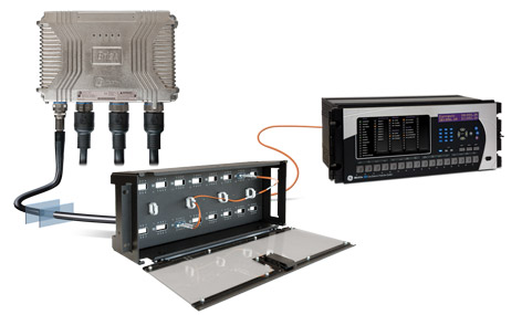
The T60’s IEC 61850 Process Bus module is designed to interface with the Multilin HardFiber System, allowing bi-directional IEC 61850 fiber optic communications. The HardFiber System is designed to integrate seamlessly with existing Universal Relay applications, including protection functions, FlexLogic, metering and communications. Learn more
The T60 can also connect to GE Vernova MU320 or third-party merging units using standard IEC 61869 or IEC 61850-9-2LE communication protocols.
Cyber Security - CyberSentry™ UR (FW v7.4xx)
CyberSentry enables UR devices to deliver full cyber security features that help customers to comply with NERC CIP and NITIR 7628 cyber security requirements through supporting the following core features:
Secure FW upgrade
UR FW files v7.9 and up now include a hash code that allows for authentication prior to being used for upgrading UR devices.
Password Complexity
Supporting up to 20 alpha- numeric or special characters, UR passwords exceed NERC CIP requirements for password complexity. Individual passwords per role are available.
AAA Server Support (Radius)
Enables integration with centrally managed authentication and accounting of all user activities and uses modern industry best practices and standards that meet and exceed NERC CIP requirements for authentication and password management.
Role Based Access Control (RBAC)
Efficiently administrate users and roles within UR devices. The new and advanced access functions allow users to configure up to five roles for up to eight configurable users with independent passwords. The standard “Remote Authentication Dial In User Service” (Radius) is used for authentication.
Event Recorder (Syslog for SEM)
Capture all cyber security related events within a SOE element (login, logout, invalid password attempts, remote/local access, user in session, settings change, FW update, etc), and then serve and classify data by security level using standard Syslog data format. This enables UR devices integration with established SEM (Security Event Management) systems.
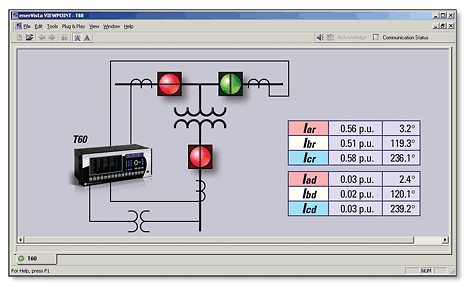
EnerVista™ Software
The EnerVista™ suite is an industry-leading set of software programs that simplifies every aspect of using the T60 relay. The EnerVista™ suite provides all the tools to monitor the status of the protected asset, maintain the relay, and integrate information measured by the T60 into DCS or SCADA monitoring systems. Convenient COMTRADE and Sequence of Events viewers are an integral part of the UR setup software included with every UR relay, to carry out postmortem event analysis and ensure proper protection system operation. Learn More
Recommended Products & services
MiCOM P642/3/5 Agile
Part of the MiCOM P40 platform, the Agile P64x transformer protection relays helps...
View More
Multilin T60
The T60 is designed for various power applications, including autotransformers, generator...
View More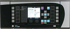
P64 MiCOM 5th Generation
Transformer Protection Relays - P642, P643, P645 The P64, part of the MiCOM P40 Agile 5th...
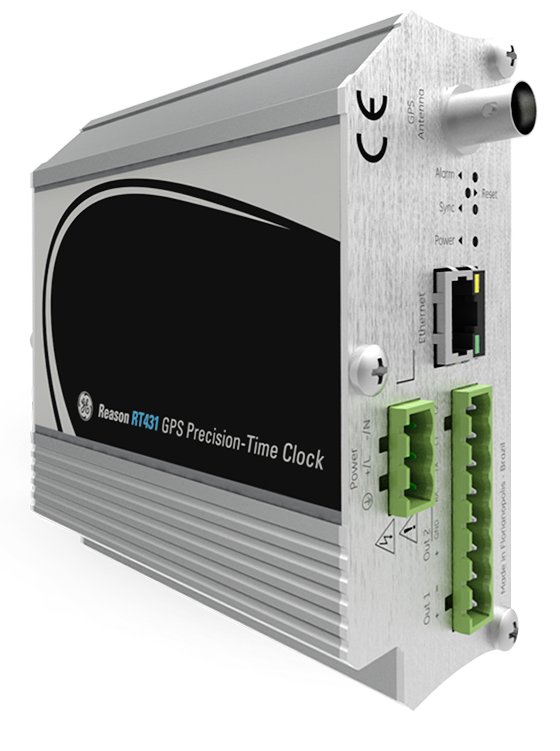
View MoreReason RT431
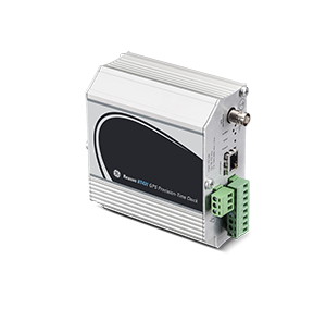
GPS Precision-Time Clock
RT431 Time Code Generator is a compact GPS-based clock designed to be installed on a DIN rail that supports the Precise Time Protocol (IEEE 1588 PTP) version 2. PTP provides accurate synchronization over Ethernet networks within 100 ns accuracy, enabling applications like synchrophasors without the need to use separate IRIG-B and PPS networks. RT431 configured as PTP slave also works as a transceiver from PTP to IRIG-B, serial or pulse time codes, enabling the use of PTP on IEDs that do not support this protocol.
Reason RT431
GPS Precision-Time Clock
RT431 Time Code Generator is a compact GPS-based clock designed to be installed on a DIN rail that supports the Precise Time Protocol (IEEE 1588 PTP) version 2. PTP provides accurate synchronization over Ethernet networks within 100 ns accuracy, enabling applications like synchrophasors without the need to use separate IRIG-B and PPS networks. RT431 configured as PTP slave also works as a transceiver from PTP to IRIG-B, serial or pulse time codes, enabling the use of PTP on IEDs that do not support this protocol.
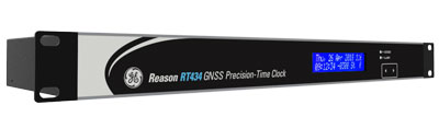
Reason RT430
GNSS Precision-Time Clocks
The demand for accurate time synchronization available 24/7 increases with the growth of critical substation applications, such as phasor measurement, merging units, traveling-wave fault location and current differential protection operating over SONET and MPLS systems. In order to yield the best accuracy and granularity from such applications, the use of a common, precision-time reference is essential.
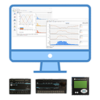
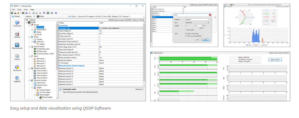
QDSP
iSTAT setting, monitoring and analysis software
QDSP is easy to use setup software for configuration of iSTAT communicating transducers, measurement centres and power quality analysers. It can store settings to ease replacement of devices or transfer/duplication of settings for equivalent applications. QDSP can also be used as a verification tool during commissioning to confirm communications and functionality such as correct measurements and inputs/outputs. For ongoing operational monitoring and analysis, QDSP also provides visualization and analysis of recorded data as well as generation of Power Quality reports.
Recommended Products & services
QDSP
QDSP is easy to use setup software for configuration of iSTAT communicating transducers,...
View MoreiSTAT M365
Power Quality Metering with Extensive Logging and Communications
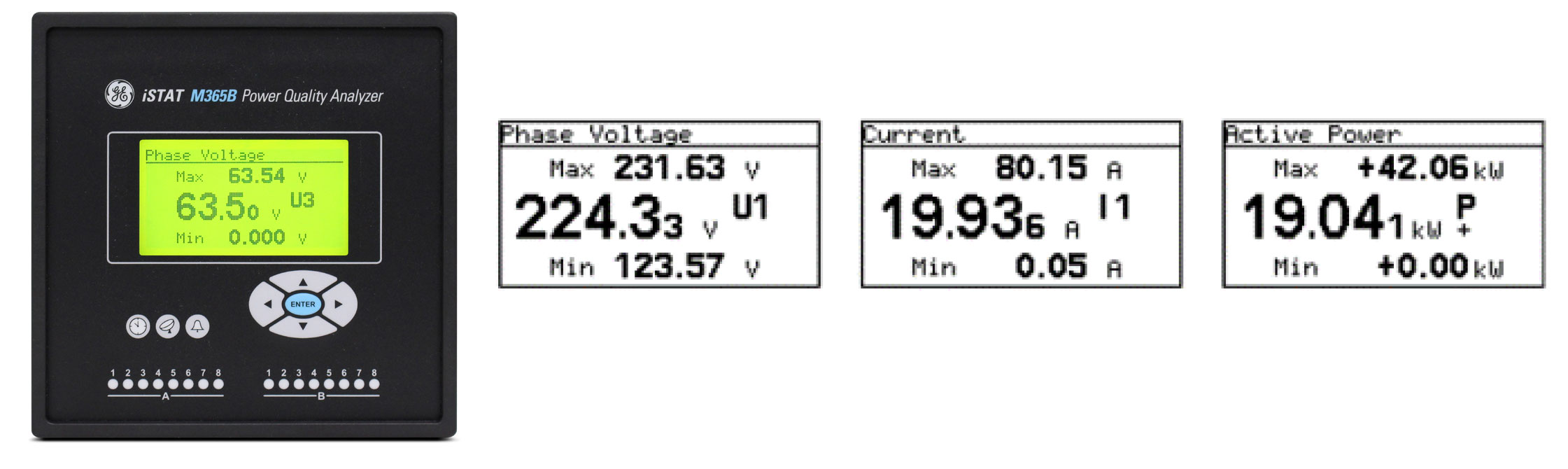
The iSTAT M365 comprehensive power quality metering and communication features are ideal for utility, industrial and commercial power quality applications. The iSTAT M365 is an enhancement to the previous iSTAT M355 offering with extensive power quality perspective with the latest IEC61000-4-30 Class A Edition 3 certification as well as supporting EN50160 reporting.
iSTAT M365
Power Quality Metering with Extensive Logging and Communications
The iSTAT M365 comprehensive power quality metering and communication features are ideal for utility, industrial and commercial power quality applications. The iSTAT M365 is an enhancement to the previous iSTAT M355 offering with extensive power quality perspective with the latest IEC61000-4-30 Class A Edition 3 certification as well as supporting EN50160 reporting.
Overview
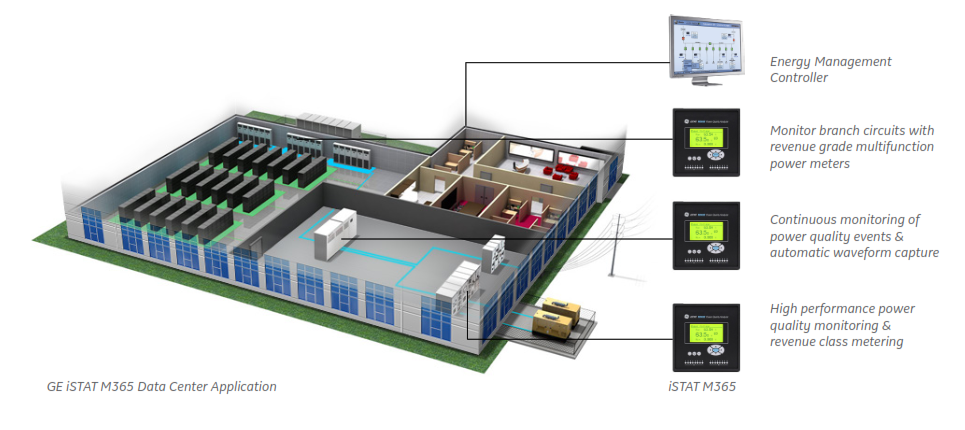
iSTAT 365 is ideal for energy and power quality monitoring in applications such as utility substations, renewables, advanced industrial manufacturing, datacenters and hospitals with the key features of:
- IEC 61000-4-30 Class A Edition 3 certification supporting the latest power quality reporting standards
- High resolution waveform recording requirements (up to 625 samples/cycle) and Class 0.2S Active energy metering accuracy with demand recording
- Standard 8GB logging memory with PQDIF and COMTRADE file storage
- Easy integration with RS232/485 Serial to support either GPS time sync or protocol communications as well as Ethernet and USB communications with protocol support for Modbus, DNP3, FTP and IEC 61850 Edition 2
- Four available I/O module slots with up to 20 I/O to support multiple customizable I/O applications
Versatile Display Options
The iSTAT M365 is available with 2 display options to best suit end user installations and data presentation requirements.
M365A - 5.7” TFT display
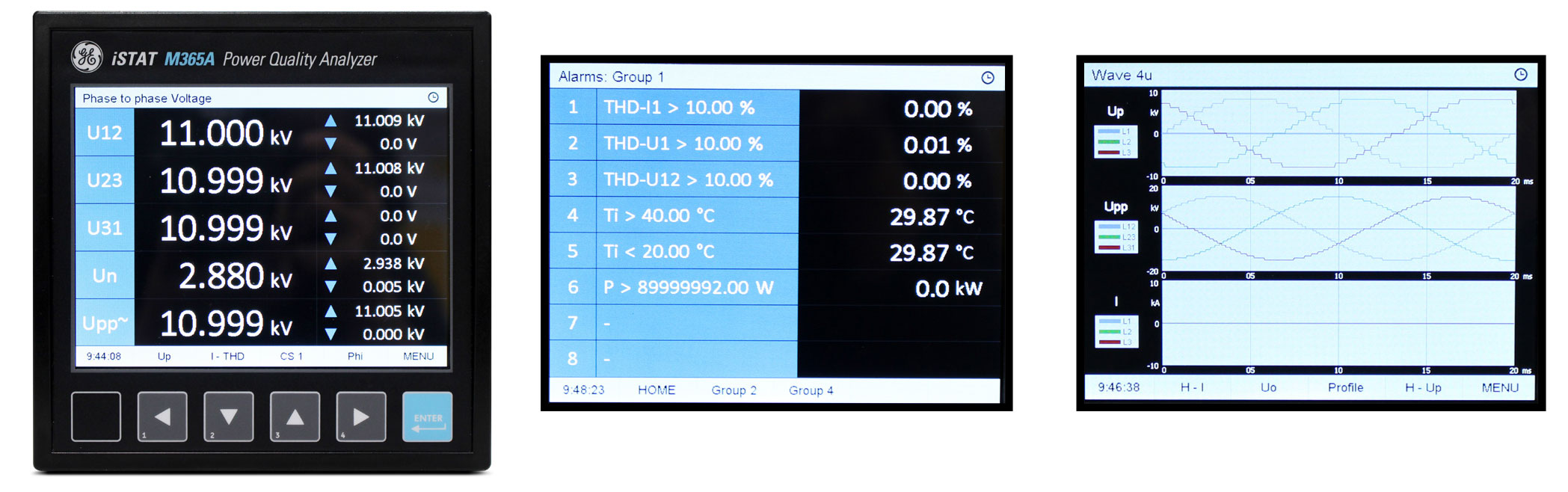
M365B - 128x64 pixel graphic LED display
Applications
- Power quality alarming/event capture for utility or industrial event investigation/reconciliation, ensuring uptime and predictive maintenance for critical power quality sensitive assets
- Accurate Class 0.2S energy measurement (demand, time of use) and for utility or industrial Applications
- High sampling data capture and control in applications such as utility generation or renewables
- Specialized utility/industrial power quality reporting for standards such as Class A IEC 61000-430 Ed.3, IEC 61000-4-15 flicker, IEC 61000-4-7 harmonics and EN50160
Software
The iSTAT M365 utilizes QDSP setup software to allow for easy initial meter setup, configuration and data visualization.
Time Sync
The iSTAT M365 support multiple types of time synchronization to ensure accuracy and synchronization of various measurements and events to meet standards.
GE Vernova Reason RT43x GNSS clocks are recommended to provide accurate time synchronization.
GPS time synchronization (PPS and NMEA)
- 1pps and serial RS232 communication with NMEA 0183 sentence support
- The interface is designed as 5 pole pluggable terminal (+5V for receiver supply, 1pps input and standard RS232 communication interface)
IRIG time code B (IRIG-B)
- Unmodulated (DC 5V level shift) and modulated (1 kHz) serial coded format with support for 1pps, day of year, current year and straight seconds of day as described in standard IRIG-200-04. GE Vernova Reason RT43x GNSS clocks recommended for time synchronization
- Supported serial time code formats are IRIG-B007 and IRIG-B127 Interface for modulated IRIG-B is designed as BNC-F terminal with 600 Ohm input impedance
- Interface for unmodulated IRIG-B is designed as pluggable terminal
Network time protocol (NTP)
- Synchronization via Ethernet requires access to a NTP server
Note: NTP can usually maintain time to within tens of milliseconds over the public Internet, but the accuracy depends on infrastructure properties - asymmetry in outgoing and incoming communication delay affects systematic bias. It is recommended that dedicated network rather than public network is used for Synchronization purposes.
Communications
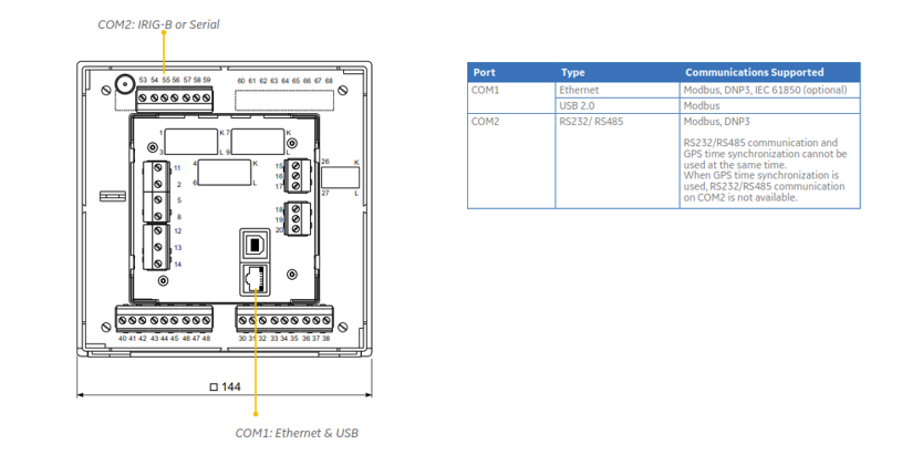
The iSTAT M365 supports various communications connections and protocols for easy integration. It is equipped with standard communication port COM1 (Ethernet & USB) and an auxiliary communication port COM2 (RS232/RS485).
Technical Specifications
| VOLTAGE MEASUREMENTS |
|---|
|
| CURRENT MEASUREMENTS |
|---|
|
| FREQUENCY MEASUREMENTS |
|---|
|
| MEASUREMENT METHOD |
|---|
|
| ACCURACY RATINGS |
|---|
|
| UNIVERSAL POWER SUPPLY | |
|---|---|
| • Standard (high): | CAT III 300 V |
| • Nominal voltage AC: | 80 … 276 V |
| • Nominal frequency: | 40 … 65 Hz |
| • Nominal voltage DC: | 80 … 300 V |
| • Consumption: | < 8 VA typical |
| < 12 VA max. loaded I/O options | |
| • Power-on transient current: | < 20 A ; 1 ms |
| TIME SYNCHRONIZATION INPUT | |
|---|---|
| • Digital input: | GPS or IRIG-B TTL |
| • 1pps voltage level: | TTL level (+5 V) |
| • Time code telegram: | RS232 (GPS) |
| DC level shift (IRIG-B) | |
| • AM analogue input: | IRIG-B AM modulated |
| • Carrier frequency: | 1 kHz |
| • Input impedance: | 600 Ohms |
| • Amplitude: | 2.5VP-Pmin, 8VP-Pmax |
| • Modulation ratio: | 3:1 – 6:1 |
| COMMUNICATION |
|---|
|
| MECHANICAL |
|---|
|
| ENVIRONMENTAL |
|---|
|
| COMPLIANCE |
|---|
|
| SAFETY |
|---|
|
* future release
Recommended Products & services
<span class="text-lowercase">i</span>STAT M2<span class="text-lowercase">x</span>2
The iSTAT M2x2 family includes: M212 Multifunction Meter - Manufacturing for the M212 has...
View More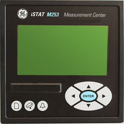
<span class="text-lowercase">i</span>STAT M2<span class="text-lowercase">x</span>3
The iSTAT M2x3 family includes: M233 Measurement Centre M243 Network Recorder -...
View More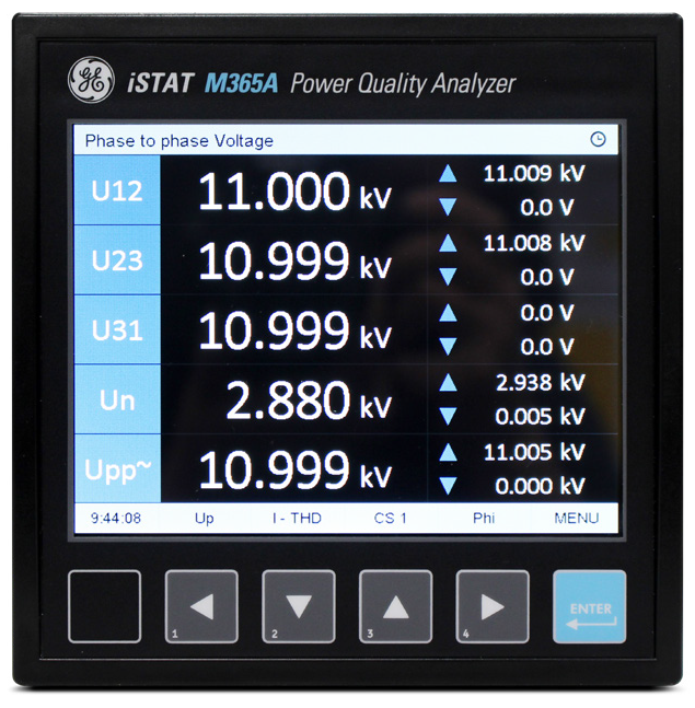
<span class="text-lowercase">i</span>STAT M365
Power Quality Metering with Extensive Logging and Communications The iSTAT M365...
View MoreiSTAT M2x3
High Performance Measurement Centre
The iSTAT M2x3 family includes:
iSTAT M2x3
High Performance Measurement Centre
The iSTAT M2x3 family includes:
Recommended Products & services
<span class="text-lowercase">i</span>STAT M2<span class="text-lowercase">x</span>2
The iSTAT M2x2 family includes: M212 Multifunction Meter - Manufacturing for the M212 has...
View More
<span class="text-lowercase">i</span>STAT M2<span class="text-lowercase">x</span>3
The iSTAT M2x3 family includes: M233 Measurement Centre M243 Network Recorder -...
View More
<span class="text-lowercase">i</span>STAT M365
Power Quality Metering with Extensive Logging and Communications The iSTAT M365...
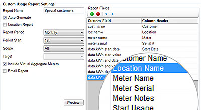
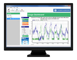
View MoreEnergy Aggregator
Energy Visualization, Analysis and Reporting Software Solution
GE Vernova’s Energy Aggregator allows facility managers to effectively manage energy ownership through automated meter data collection, visualization of key data for better decision making, and fair billing and reporting for financial environmental incentives. With Energy Aggregator’s accurate and easy to understand energy reporting, tenant satisfaction is also improved.
Energy Aggregator
Energy Visualization, Analysis and Reporting Software Solution
GE Vernova’s Energy Aggregator allows facility managers to effectively manage energy ownership through automated meter data collection, visualization of key data for better decision making, and fair billing and reporting for financial environmental incentives. With Energy Aggregator’s accurate and easy to understand energy reporting, tenant satisfaction is also improved.
Comprehensive Energy Visualization
Energy Aggregator provides a complete picture of energy usage with valuable data-based insight and analysis to improve tenant satisfaction and increase energy ownership.
- Easy to understand, visual dashboard views to provide trending reporting and comparison analysis over time
- Determine inefficiencies and savings opportunities, to reduce energy demand by centrally and accurately collecting and visualizing data
- Provide accurate, data-based insight to tenants to increase ownership and change energy consumption
- Centralize collection for a complete view of energy consumption including electrical, water, air, gas, steam, etc.
- Compare energy consumption with location based weather data
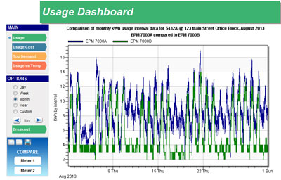 Compare energy usage between different areas over time periods
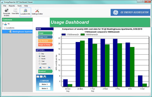 Compare cost data between metered areas
Automated Report Generation
Energy Aggregator provides standardized and customizable reports that are automatically generated and distributed to decision makers and management, enabling constant awareness.
- Standardized and customizable reports provide insight on high-value aspects of energy consumption to make effective decisions
- Automated report generation and distribution ensures accurate, consistent reporting and constant awareness with low resource effort
- Easily baseline, determine and pinpoint opportunities for savings and energy improvements
- Example reports include:
- Usage Summaries
- Location-based Temperature Impact on Usage/Demand
- Monthly/Yearly Meter Comparisons
- Peak Day/Week Profile
- Average Hourly/Daily Usage
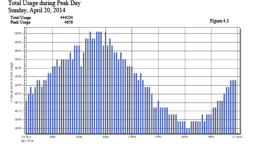 Generate reports to visualize and analyze total and peak
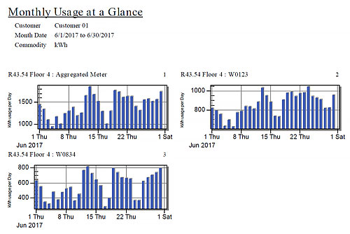 Generate reports to visualize energy usage
Automated Energy Billing
Energy Aggregator generates standardized and customizable bills with support for rate structures and charges. Generated bills can be sent and distributed automatically to users as per a defined interval reducing resource efforts and costs involved with engaging other billing service providers.
- Standardized and customizable billing provides fair billing based on energy consumption
- Automated bill generation and distribution ensures accurate, consistent reporting and ownership with low resource effort and eliminates need to engaging billing service providers
- Support for rates structures such as fixed, tiered or TOU rates (fixed, seasonal) as well as additional charges, taxes
- Ability to bill completely for energy as well as other commodities such as Water, Air, Gas, and Steam
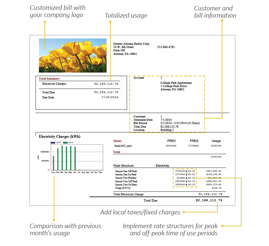 Generate and distribute standardized and customizable bills
Simplified Commissioning & Lower Cost of Ownership
Energy Aggregator is designed with functionality to make both initial setup and ongoing maintenance of the system easy for users.
- Automated discovery of meters eliminates setup errors and reduces configuration challenges
- Reduces initial commissioning efforts and ongoing operating and maintenance costs with automated setup, report email functionality and application updates
- Easy to use reporting setup for customized report formats or export to other systems
 Easily add meters through MeterManager auto scan functionality
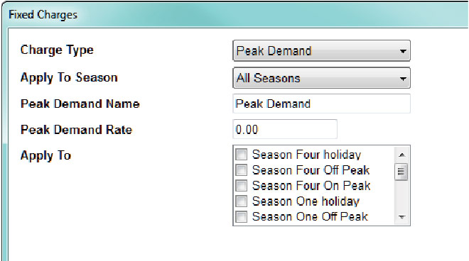 Simple configuration of peak demand charges
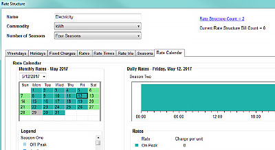 Visually confirm rate structure setup
 User-friendly report/bill configuration
System Requirements
| Components | Requirements |
|---|---|
| Supported Operating Systems |
|
| Computer and Processor |
|
| Memory |
|
| Other |
|
T155 Dual Gas GIS
SF₆ and g³ Gas-Insulated Substations up to 420 kV
GE Vernova's T155 Dual Gas GIS meets the challenges of networks up to 420 kV for power generation, transmission, and heavy industry applications.
Ready for future SF₆ gas regulations
Anticipating future SF₆ regulations, this Dual-Gas equipment is available with either g³ or SF₆ gas as an insulating and switching medium. Based on having the same foundational design, Transmission System Operators (TSOs) can buy the SF₆ version today and easily switch to GE Vernova’s g³ solution at a later time.
Transition from SF₆ to g³ technology today to reach your carbon neutrality targets faster. Compare the carbon footprint of your substation using g³ products in place of SF₆.

Customer Benefits

Characteristics
Sustainability
- 100% SF₆-free version available with T155 Dual Gas GIS (with g³ gas)
- The gas contribution to global warming is reduced by 99% using GE Vernova’s g³ gas instead of SF₆
- First-in-class gas sealing system
- Improved tightness due to sealing length divided by two, compared to the previous version
High availability
- Current transformers located outside SF₆/g³ gas compartment
- Pure-spring circuit breaker drives
- State-of-the-art maintenance isolating device: major repair and HV tests with no more than one bay down
- Outstanding accessibility to drives and accessories
Low costs of land and civil works
- Very compact GIS: bay footprint remains the same as latest SF₆ GIS
Short site works
- Complete bays are fully assembled in the factory (wired, tested, packaged, and shipped)
Smart grid features
- Full-digital monitoring, control and protection
Specifications
| g³ | Combined g³ bay-SF₆ CB | SF₆ | |
GIS Type | T155g 420 kV | T155 420 kV | T155 420 kV |
| Reference electrotechnical standards | IEC | IEC/IEEE | IEC/IEEE |
| Rated voltage | 362-420 kV | 362-420 kV | 362-420 kV |
| Withstand voltages | |||
| Short-duration power-frequency, phase-to-earth/across open switching device | 650/815 kV | 650/815 kV | 650/815 kV |
| Switching impulse, phase-to-earth / across isolating distance | 1050/900(+345) kVp | 1050/900(+345) kVp | 1050/900(+345) kVp |
| Lightning impulse, phase-to-earth / across open switching device | 1425/1425(+240) kVp | 1425/1425(+240) kVp | 1425/1425(+240) kVp |
| Frequency | 50 Hz | 50/60 Hz | 50/60 Hz |
| Continuous current | up to 5000 A | up to 5000 A | up to 5000 A |
| Short-time withstand current | 63 kA | 63 kA | 63 kA |
| Peak withstand current | 170 kAp | 170 kAp | 170 kAp |
| Duration of short-circuit | 3s | 3s | 3s |
| Installation | indoor/outdoor | indoor/outdoor | indoor/outdoor |
Circuit Breaker Ratings | |||
| Short-circuit breaking current | 63 kA | 63 kA | 63 kA |
| Short-circuit making current | 170 kAp | 170 kAp | 170 kAp |
| Operating sequence | O-0.3s-CO-3 min-CO/CO-15s-CO | O-0.3s-CO-3 min-CO/CO-15s-CO | O-0.3s-CO-3 min-CO/CO-15s-CO |
| Drive type | Pure-spring | Pure-spring | Pure-spring |
| Mechanical endurance | M2 class | M2 class | M2 class |
| Capacitive switching | C2 class | C2 class | C2 class |
Disconnector and Low-speed Earthing Switch Ratings | |||
| Capacitive current switching | 0.5 A | 0.5 A | 0.5 A |
| Bus-transfer current switching capability | 3000 A / 20 V | 3000 A / 20 V | 3000 A / 20 V |
| Mechanical endurance | M2 class | M2 class | M2 class |
Make-proof Earthing Switch Ratings | |||
| Making current capability | 170 kAp | 170 kAp | 170 kAp |
| Switching capability-electromagnetic coupling | 160 A / 10 kV | ||
| Switching capability-electrostatic coupling | 18 A / 20 kV | 18 A / 20 kV | 18 A / 20 kV |
| Mechanical endurance | M1 class | M1 class | M1 class |
Recommended Products & services

F35 72.5 <span class="text-lowercase">k</span>V GIS for Wind Turbines
Welcome to the Future of Wind Power: 72.5 kV Gas-Insulated Substations The offshore wind...
View More
SF₆ and g³ Gas-Insulated Substations
GE Vernova provides GIS solutions from 50 kV to 800 kV, along with smart devices to...
View More
B105 Dual Gas GIS
The B105g SFâ-free GIS is part of GRiDEA, our portfolio of solutions designed to...
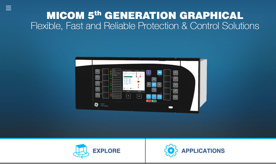
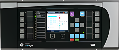
View MoreMiCOM Agile P140 Series
Feeder Protection Relay - P141, P142, P143, P144, P145
Part of the MiCOM P40 platform, the Agile P14x feeder management relays provide an integrated solution for the complete protection, control and monitoring of overhead lines and underground cables, covering all distribution and transmission voltage levels. Providing all essential information to efficiently maintain complex power systems and their components, the P14x relay family is user-friendly and highly flexible, allowing application on any electrical network.
MiCOM Agile P140 Series
Feeder Protection Relay - P141, P142, P143, P144, P145
Part of the MiCOM P40 platform, the Agile P14x feeder management relays provide an integrated solution for the complete protection, control and monitoring of overhead lines and underground cables, covering all distribution and transmission voltage levels. Providing all essential information to efficiently maintain complex power systems and their components, the P14x relay family is user-friendly and highly flexible, allowing application on any electrical network.
What's New
Overview
- 4-stages of non-directional/directional overcurrent, earth fault, negative phase sequence overcurrent, sensitive earth fault protection
- 2-stage under/over voltage, 9-stage under/overfrequency, check synchronism, autoreclose and breaker fail
- IEC 61850 redundant Ethernet, with RSTP and IEC 62439 PRP and HSR – with HSR support for up to 50 nodes in a ring
- Graphical programmable scheme logic eases protection scheme creation and avoids the need for external logic controllers
- Hardware modularity extends up to a maximum of 48 binary (opto) inputs
- Integrated functionality permits control of up to eight switchgear elements in the bay, in addition to circuit breaker control
Key benefits:
- Comprehensive library of hardware options, protection and control functions suitable to meet your system requirements
- Advanced autoreclose and synchronizing options, including predictive closing such that CB primary contacts touch near to the exact moment that systems drift in-phase
- The standard and user-programmable curves, supplemented by load blinders and voltage supervision offer fast and dependable fault tripping, without constraining circuit loadability
- Distance to fault location assists dispatching of maintenance crews
Functional Block diagram
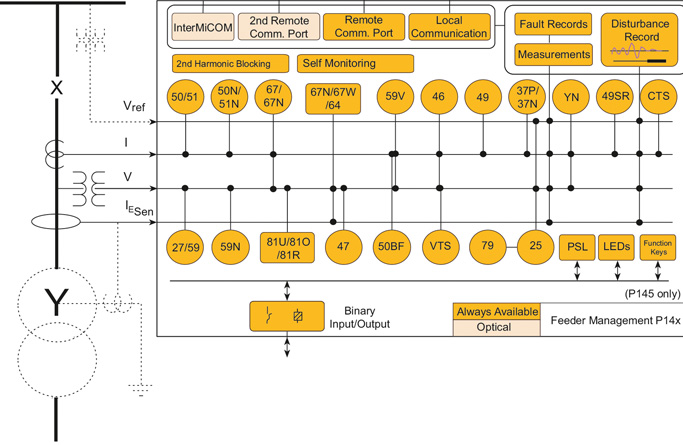
ANSI ® Device Numbers and Functions
| Device Number | Function |
|---|---|
| 25 | Check Synchronising |
| 27 | Phase and Line Undervoltage |
| 32 | Phase Directional Power |
| 37 | Undercurrent |
| 46 | Negative Sequence Overcurrent |
| 47 | Negative Sequence Overvoltage |
| 49 | Thermal Overload |
| 50/27 | Switch-on to Fault |
| 50 | Phase Definitive Time Overcurrent |
| 51 | Phase Inverse-Time Overcurrent |
| 52 | Breaker and Isolator Control |
| 59 | Phase and Line Overvoltage |
| dv/dt | Rate of Change of Voltage |
| 67 | Directional Phase Overcurrent |
| 68 | Inrush Blocking |
| Device Number | Function |
|---|---|
| 79 | Autoreclose |
| 85 | InterMiCOM Teleprotection |
| 86 | Latching/Lockout Contacts |
| 87 | High-Impedance Busbar Differential |
| 21BL | Load Encroachment/Blinder |
| 21FL | Fault Locator |
| 32S | Sensitive Power |
| 46BC | Broken Conductor |
| 49SR | Silicon Rectivier Thermal |
| 50BF | CB Failure |
| 50N | Earth Fault Definitive Time Overcurrent |
| 51N | Neutral/Ground IDMT Overcurrent |
| SEF | Sensitive Earth Fault, I cos and I sin |
| 51R | Voltage Restrained Overcurrent |
| 51V | Voltage Controlled Overcurrent |
| Device Number | Function |
|---|---|
| PSL | Programmable Logic |
| CLP | Cold Load Pick Up |
| 59N | Neutral Voltage Displacement |
| 59S | Busbar Buswire Supervision |
| 64N | Restricted Earth Fault |
| 67N | Directional Neutral/Ground Overcurrent |
| 67W | Wattmetric Earth Fault |
| 81df/dt | Rate of Change Frequency |
| 81O | Overfrequency |
| 81R | Load Restoration |
| 81U | Underfrequency |
| 81V | Undervoltage Blocking |
| CTS | CT Supervision |
| VTS | VT Supervision |
| YN | Neutral Admittance |
Agile P14x Models Available
- P141 Feeder management IED
- P142 Feeder management IED with autoreclose
- P143 Feeder management IED with autoreclose and synchronizing
- P144 Feeder management IED with transient earth fault detection for isolated/Petersen systems
Manufacturing for P144 has been discontinued. As an alternative, please refer to P84. - P145 Feeder management IED with autoreclose, synchronizing and function keys
MiCOM S1 Agile
Key benefits:
- Powerful, free of charge, PC toolsuite
- Optimum management of the installed base, structured as per the substation topology
- Intuitive and versatile interface with file management facilities
- Logical structure based on substation, voltage level and bay
- Version control and cross-checking facilities for IED settings
- Real-time measurement visualization – MiCOM S1 Agile extends to all MiCOM Agile IEDs - including P847 PMU and busbar schemes
Engineering Tool Suite
S1 Agile is the truly universal PC tool for MiCOM Agile relay, assemble all tools in a palette for simple entry, with intuitive navigation via fewer mouse-clicks. No-longer are separate tools required for redundant Ethernet configuration, phasor measurement unit commissioning, busbar scheme operational dashboards, programmable curve profiles or automatic disturbance record extraction – applications are embedded. MiCOM S1 Agile supports all existing MiCOM, K-Series and Modulex, including a utility for automatic conversion of setting files from previous generations of numerical relays like K-series and MiCOM P20 to the latest P40 Agile models.
To move to the future, with no loss of functionality, no loss of device support, and full compatibility with your installed base and system architecture – request a copy of S1 Agile with the contact form link below.
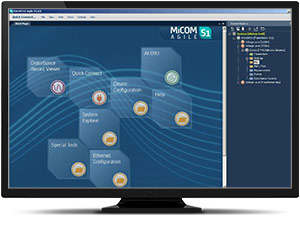
Key features in the MiCOM S1 family:
- GE Vernova’s integrated engineering tool that provides users with access to automation IED configuration and record data
- Integrated configuration and monitoring features
- Send and extract setting files
- Event and disturbance record extraction and analysis
MiCOM S1 Agile software request
To receive the MiCOM S1 Agile, please use our Contact form. This will also ensure that you are kept up-to-date with the latest enhancements, including updates and bug fixes.
Refurbishment Solutions – “If It’s Blue Think to Renew”
GE Vernova’s latest MiCOM P140 series models P141 to P145 inclusive offer an ideal path to refurbish an older installed base of MiCOM P140 relays. Whether those older products were initially sold as GE VERNOVA or AREVA-branded products, newer models retain pin-pin refurbishment capability. Advantageously, users can benefit from the advancements made in protection, control, communications, hardware and cybersecurity that have taken place in the intervening years. The new P40 retains form, fit and function compatibility but delivers the latest platform and software ready for today’s environment, and for future-proofed application for the decades ahead.
Pin-Pin Upgrade Methodology:
- Take the order code (CORTEC) of the older relay being removed, typically a blue case relay
- Translate to today’s latest GE Vernova MiCOM model, adding Ethernet options if required
- Order the new P40 relay
- Extract settings and logic, use S1 Agile toolsuite to convert settings
- Detach the terminal blocks from old relay, leaving wiring attached / detach terminal blocks from the new.
- Carefully examine the terminal blocks to see that no physical damage has occurred since installation
- Mount new relay. Old relay blocks fit straight onto the new relay - safer, less wiring to reconnect.
- It is recommended to apply rated current and voltage to the relay CT/VT inputs during secondary injection testing to check the continuity of the CT/VT terminal block connections to the relay.
- Download converted files
- Test, return circuit to service with only minutes of downtime
Recommended Products & services
P84 MiCOM 5th Generation
The P84, part of the MiCOM P40 Agile 5th Generation family, is a multi-functional line...
View More
Multilin F60
The F60, a member of the UR Family of protection relays, provides high performance feeder...
View More
MiCOM Agile P140 Series
Part of the MiCOM P40 platform, the Agile P14x feeder management relays provide an...
View MoreMiCOM Agile P747
Centralized Busbar Differential Relay
The MiCOM Agile P747 provides complete protection for voltage levels up to extra high voltage busbar configurations with a centralized 3-box architecture. The MiCOM Agile P747 can accommodate up to 4 zones plus check zone and protect up to 18 terminals. The MiCOM Agile P747 Is particularly useful in double busbar with double bus coupler applications and allows a high number of opto inputs, relay outputs, and virtual inputs and outputs to manage the complete substation scheme.
MiCOM Agile P747
Centralized Busbar Differential Relay
The MiCOM Agile P747 provides complete protection for voltage levels up to extra high voltage busbar configurations with a centralized 3-box architecture. The MiCOM Agile P747 can accommodate up to 4 zones plus check zone and protect up to 18 terminals. The MiCOM Agile P747 Is particularly useful in double busbar with double bus coupler applications and allows a high number of opto inputs, relay outputs, and virtual inputs and outputs to manage the complete substation scheme.
What's New
Overview
- Typical operating time of 17 ms with standard contacts
- Phase segregated biased current differential high speed busbar protection
- Easy maintenance, operation and future expansion of the busbar supported
- Deploy in ring-bus/mesh corners, single busbars, sectionalized busbars, and one per bus in breaker and a half topologies
- Adapted to all kinds of busbar configurations
Key benefits:
- 3 boxes (one per phase) for large schemes up to 18 terminals
- Interoperable with all classes of CT: IEEE, IEC, air-gapped, non-gapped, and CTs with moderate knee point voltage
- 10 integrated function keys, tri-color LEDs, and graphical programmable logic permit the creation of comprehensive schemes, tailored to your needs
- IEC 61850 redundant Ethernet, supporting self healing ring, RSTP, dual homing, PRP or HSR
Functional Block Diagram
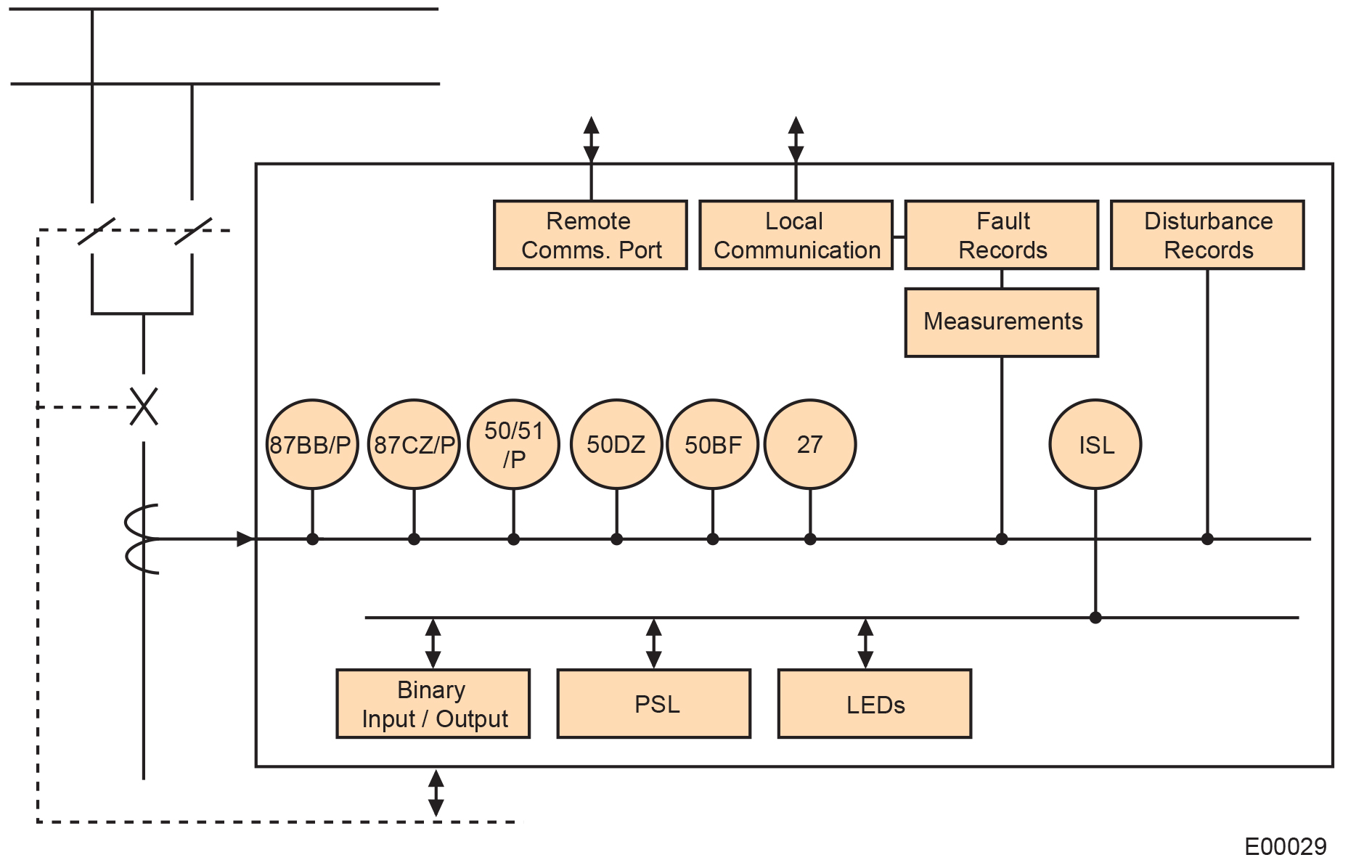
ANSI© Device Numbers and Functions
| Device Number | Function |
|---|---|
| 87BB | Bus Differential |
| 50 | Phase Definite Time Overcurrent |
| 51 | Phase Inverse-Time Overcurrent |
| 86 | Latching/Lockout Contacts |
| 50BF | CB Failure |
| VTS | VT Supervision |
MiCOM S1 Agile
Key benefits:
- Powerful, free of charge, PC toolsuite
- Optimum management of the installed base, structured as per the substation topology
- Intuitive and versatile interface with file management facilities
- Logical structure based on substation, voltage level and bay
- Version control and cross-checking facilities for IED settings
- Real-time measurement visualization – MiCOM S1 Agile extends to all MiCOM Agile IEDs - including P847 PMU and busbar schemes
Engineering Tool Suite
S1 Agile is the truly universal PC tool for MiCOM Agile relay, assemble all tools in a palette for simple entry, with intuitive navigation via fewer mouse-clicks. No-longer are separate tools required for redundant Ethernet configuration, phasor measurement unit commissioning, busbar scheme operational dashboards, programmable curve profiles or automatic disturbance record extraction – applications are embedded. MiCOM S1 Agile supports all existing MiCOM, K-Series and Modulex, including a utility for automatic conversion of setting files from previous generations of numerical relays like K-series and MiCOM P20 to the latest P40 Agile models.
To move to the future, with no loss of functionality, no loss of device support, and full compatibility with your installed base and system architecture – request a copy of S1 Agile with the contact form link below.
Key features in the MiCOM S1 family:
- GE Vernova’s integrated engineering tool that provides users with access to automation IED configuration and record data
- Integrated configuration and monitoring features
- Send and extract setting files
- Event and disturbance record extraction and analysis
MiCOM S1 Agile software request
To receive the MiCOM S1 Agile, please use our Contact form. This will also ensure that you are kept up-to-date with the latest enhancements, including updates and bug fixes.
MiCOM Agile P747 Remote HMI PC Application Software
MiCOM Agile P747 remote PC HMI provides the following features:
- P747 Remote HMI allows the user to display the MiCOM Agile P747 measured analogue quantities and DDB (digital data bus) status information dynamically via the user defined busbar topology
Please use our Contact form to request the software.
Refurbishment Solutions
Refurbishment Solutions – “If It’s Blue Think to Renew”
GE Vernova’s latest MiCOM P747 model offers an ideal path to refurbish an older installed base of MiCOM P747 relays. Whether those older products were initially sold as GE VERNOVA or AREVA-branded products, newer models retain pin-pin refurbishment capability. Advantageously, users can benefit from the advancements made in protection, control, communications, hardware and cybersecurity that have taken place in the intervening years. The new P40 retains form, fit and function compatibility but delivers the latest platform and software ready for today’s environment, and for future-proofed application for the decades ahead.
Pin-Pin Upgrade Methodology:
- Take the order code (CORTEC) of the older relay being removed, typically a blue case relay
- Translate to today’s latest GE Vernova MiCOM model, adding Ethernet options if required
- Order the new P40 relay
- Extract settings and logic, use S1 Agile toolsuite to convert settings
- Detach the terminal blocks from old relay, leaving wiring attached / detach terminal blocks from the new.
- Carefully examine the terminal blocks to see that no physical damage has occurred since installation
- Mount new relay. Old relay blocks fit straight onto the new relay - safer, less wiring to reconnect.
- It is recommended to apply rated current and voltage to the relay CT/VT inputs during secondary injection testing to check the continuity of the CT/VT terminal block connections to the relay.
- Download converted files
- Test, return circuit to service with only minutes of downtime
Contact us for advice and support
Recommended Products & services
Multilin B90
The Multilin B90 bus protection relay, a member of the UR Family, features integrated...
View More
MiCOM Agile P746
The MiCOM Agile P746 provides complete protection for MV and HV busbar configurations...
View More
MiCOM Agile P747
The MiCOM Agile P747 provides complete protection for voltage levels up to extra high...
View More