Support a variety of substation automation & control, comms and monitoring applications
Category image
Has legacy products
On
Overview
Overview Back Link
Support a variety of substation automation & control, comms and monitoring applications
Manufacturing for the 850R has been discontinued. As an alternative, please refer to the R650.
Manufacturing for the 850R has been discontinued. As an alternative, please refer to the R650.
The role of a recloser in a distribution network has developed in line with the increasing need for operators to minimize outage duration and the numbers of customers affected by faults, which in turn helps maximize performance according to reliability indices like CAIDI/SAIDI. As a result, it has two main functions. Its primary function is to clear the fault when it occurs as quickly as possible. Secondly, if the fault is permanent, the recloser takes on a sectionalising role driven by logic or commands. These control systems are dependent on the data delivered by the recloser on three levels: general monitoring from a historic perspective, fault data at the time of fault and pre/post fault data.
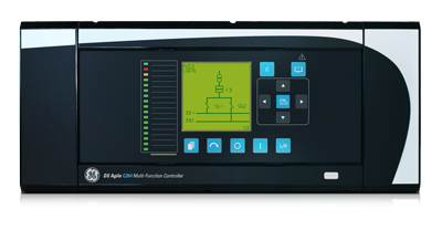
Multifunction Distribution Automation Controller with Recloser/Switch/Sectionalizer (Tie-Bus) control for overhead applications
From simple automation to advanced analytics, the 850R provides the flexibility and scalability required to meet unique application requirements for the distribution utilities.
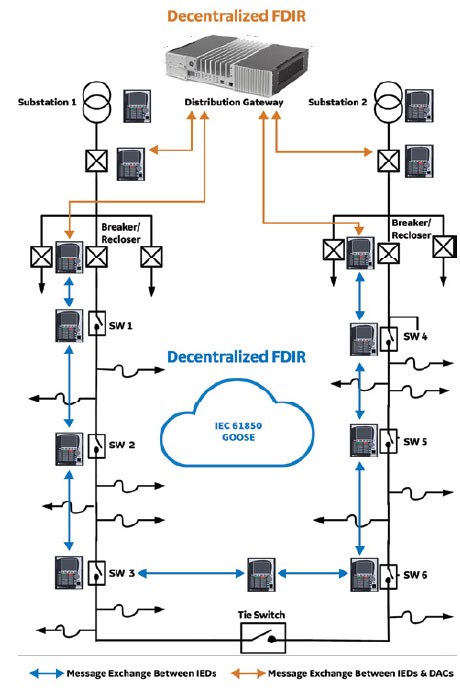
The decision making algorithm utilized in Distributed FDIR is spread among the field devices in the covered area using IEC 61850 GOOSE multicast. This approach eliminates the need for a centralized or decentralized system, and therefore reduces the total cost. Since this approach uses IEC 61850 GOOSE peer-to-peer communication messages among the field devices, it can be much faster and cost effective than other options.
Decentralized FDIR is a model-based scheme with the decision making algorithm residing at the substation level rather than the DMS level. The substation controllers, known as Distribution Automation Controllers (DACs), can also send the received data to the DMS level for supervisory monitoring and control in a more efficient manner. Automation applications, such as IVVC, can still be added at the substation level. The 850R supports redundant Ethernet and fiber port physical interface options and a wide range of industry standard protocols for communication, namely Modbus TCP/IP, DNP 3.0, IEC 60870-5-101, IEC 60870-5-103, IEC 60870-5-104, IEC 61850 ED2, IEC 62439 / PRP.
The 850R provides secure and reliable protection & autoreclose functionality by offering a comprehensive range of standard and advanced protection and control elements. The controller provides directional and non-directional overcurrent protection along with the option of single-phase tripping and reclosing. Additionally, voltage and frequency protection elements may be used to disconnect Distributed Energy Resources (DER).
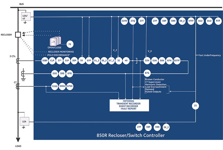
| Device Number | Function |
|---|---|
| 21YN | YN Neutral Admittance |
| 25 | Synchrocheck |
| 27P | Phase Undervoltage |
| 27Q | UV Reactive Power |
| 27T | Timed Undervoltage Protection |
| 27X | Auxiliary Undervoltage |
| 32 | Directional Power |
| 32N | Wattmetric Ground Fault (Wattmetric zero sequence directional) |
| 37 | Undercurrent |
| 49 | Thermal Overload |
| 50BF | Breaker Failure |
| 50G | Ground Instantaneous Overcurrent |
| 50SG | Sensitive Ground Instantaneous Overcurrent |
| 50N | Neutral Instantaneous Overcurrent |
| 50P | Phase Instantaneous Overcurrent |
| 50_2 | Negative Sequence Instantaneous Overcurrent |
| 51G | Ground Time Overcurrent |
| Device Number | Function |
|---|---|
| 51SG | Sensitive Ground Time Overcurrent |
| 51N | Neutral Time Overcurrent |
| 51P | Phase Time Overcurrent |
| 51_2 | Negative Sequence Time Overcurrent |
| 59N | Neutral Overvoltage |
| 59P | Phase Overvoltage |
| 59X | Auxiliary Overvoltage |
| 59_2 | Negative Sequence Overvoltage |
| 67G | Ground Directional Element |
| 67SG | Sensitive Ground Directional Element |
| 67N | Neutral Directional Element |
| 67P | Phase Directional Element |
| 67_2 | Negative Sequence Directional Element |
| 79 | Automatic Recloser |
| 81O | Overfrequency |
| 81U | Underfrequency |
| Device Number | Function |
|---|---|
| 81R | Frequency Rate of Change |
| 87G | Restricted Ground Fault (RGF) |
| CLP | Cold Load Pickup |
| I1/12 | Broken Conductor |
| MCB | Manual Close Blocking |
| SOTF | Switch Onto Fault |
| TGFD | Transient Ground Fault Detection |
| VTFF | Voltage Transformer Fuse Failure |
| Auto Sectionalizer | |
| Battery Testing and Monitoring | |
| Capacitor and Coil Monitoring | |
| Fast Underfrequency | |
| Load Encroachment | |
| Overhead Switch Health Monitoring | |
| Power Loss | |
| PseudoVoltage | |
| Recloser Coil, Cap Voltage, and Health Monitoring | |
| Supply Switchover Function |
From simple automation to advanced analytics, the 850R provides the flexibility and scalability required to meet unique application requirements for the distribution utilities.
The decision making algorithm utilized in Distributed FDIR is spread among the field devices in the covered area using IEC 61850 GOOSE multicast. This approach eliminates the need for a centralized or decentralized system, and therefore reduces the total cost. Since this approach uses IEC 61850 GOOSE peer-to-peer communication messages among the field devices, it can be much faster and cost effective than other options.
Decentralized FDIR is a model-based scheme with the decision making algorithm residing at the substation level rather than the DMS level. The substation controllers, known as Distribution Automation Controllers (DACs), can also send the received data to the DMS level for supervisory monitoring and control in a more efficient manner. Automation applications, such as IVVC, can still be added at the substation level.
The 850 provides advanced communications technologies for remote data and engineering access, making it easy and flexible to use and integrate into new and existing infrastructures. Direct support for fiber optic Ethernet provide s high-bandwidth communications, allowing for low-latency controls and high-speed file transfers of relay fault and event record information. The 850 also supports two independent IP addresses, providing high flexibility for the most challenging of communication networks.
Providing several Ethernet and serial port options, dual independent Ethernet Ports, and support for a wide range of industry standard protocols, the 850 enables easy, direct integration into DCS and SCADA systems. The 850 supports the following protocols:
The 850 has two interfaces as USB front port and Wi-Fi for ease of access to the relay. Wi-Fi Connectivity:
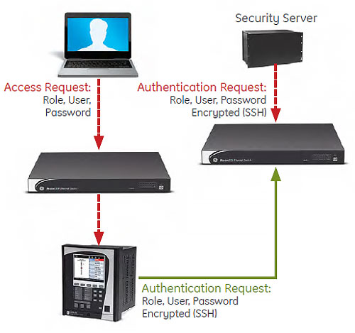
The 850 cyber security enables the device to deliver full cyber security features that help operators to comply with NERC CIP guidelines and regulations.
Enables integration with centrally managed authentication and accounting of all user activities and uses modern industry best practices and standards that meet and exceed NERC CIP requirements for authentication and password management.
Efficiently administrate users and roles within UR devices. The new and advanced access functions allow users to configure up to five roles for up to eight configurable users with independent passwords. The standard “Remote Authentication Dial In User Service” (Radius) is used for authentication.
Capture all cyber security related events within a SOE element (login, logout, invalid password attempts, remote/local access, user in session, settings change, FW update, etc), and then serve and classify data by security level using standard Syslog data format. This will enable integration with established SEM (Security Event Management) systems.
The driving electronics board checks the coil connection continuity of the trip/close circuit, as well as the leakage current to ground. When magnitude of any phase current falls below the undercurrent trip pickup level for the time specified by the undercurrent trip delay. The alarm and trip pickup levels should be set lower than the lowest feeder loading during normal operations.
The Capacitor Voltage Alarm function defines the low voltage alarm for the internal/external capacitor charging power supply circuit. This rated voltage is used for charging the external capacitors that open and close the single-pole of the recloser. If the measured voltage of the capacitors is less than the configured percentage of the rated voltage, then the Cap Volt OP operand is generated. In addition, to prevent the charger from damage due to overloading or load short faults created by incorrect wiring, bad capacitors, or hardware failures, the 850R automatically turns off the capacitor charger to prevent damage.
The 850R relay provides recloser/OHSW health information by monitoring and analyzing the operation count, arcing energy of breaking current, arcing time, opening time, and closing time when applicable. The recloser health status depends on many factors, such as permissible operation number, magnitude of breaking current, mechanical wear and contact wear.
The Time of Day Timer function provides the user with the ability to program control actions based on real time. There are two identical Time of Day Timers.
Monitoring of the total accumulated energy/accumulated demand/minimum and maximum power demand at the end of an event or a shift interval. A shift can be defined by the breaker status operand (opclosed) or operand derived from the Time of Day Timer element.
The Voltage disturbance function of Voltage Swell and Voltage Sag, as described in IEEE 1159-2009. When the voltage on any phase drops below this level a voltage sag condition occurs. Voltage sags are usually associated with system faults but can also be caused by switching heavy loads or starting large motors. Short duration voltage sag may cause process disruptions. Voltage swells are usually associated with system fault conditions, but they are much less common than voltage sags. An SLG fault on the system can cause a swell to occur, resulting in a temporary voltage rise on the healthy phases. Swells can also be caused by switching off a large load, load shedding, or switching on a large capacitor bank. Voltage swell may cause failure of the components depending upon the magnitude and frequency of occurrence.
The EnerVista™ suite is an industry-leading set of software programs that simplifies every aspect of using the Multilin 8 Series. EnerVista provides all the tools to monitor the status of the protected asset, maintain the device and integrate the information measured by the Multilin 8 Series, into SCADA or DCS process control systems. The ability to easily view sequence of events is an integral part of the setup software, as postmortem event analysis is critical to proper system management.
EnerVista Launchpad is a powerful software package that provides users with all the setup and support tools needed for configuring and maintaining Multilin products. The setup tools within Launchpad allow for the configuration of devices in real-time, by communicating via serial, Ethernet or modem connections, or offline by creating device setting files to be sent to devices at a later time. Included in Launchpad is a document archiving and management system that ensures critical documentation is up-to-date and available when needed.
8 Series Setup Software is a single setup and configuration across the platform and can reduce device setup and configuration time.
GE Vernova offers an industry-leading suite of controllers that support a variety of...
View More
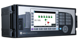
The C60 provides a complete integrated package for the protection, control, and monitoring of circuit breakers. The C60 supports dual-breaker busbar configurations such as breaker-and-a-half or ring bus arrangements. Signals from up to 4 sets of CT’s can be brought into the C60 for internal summation.
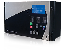
The C650 is a flexible, substation hardened, relay grade programmable logic controller. With metering and advanced communications capabilities, it is suitable for a wide range of applications. Its ability to support up to 192 digital inputs means that the C650 can also be used to extend the I/O capability of new or existing protection and control relays.
Not finding the controller product that you are looking for? View legacy controllers
GE Vernova offers an industry-leading suite of controllers that support a variety of...
View More