Support a variety of substation automation & control, comms and monitoring applications
Category image
Has legacy products
On
Overview
Overview Back Link
Support a variety of substation automation & control, comms and monitoring applications
Manufacturing for R650 has been discontinued. As an alternative, please refer to 850 or Multilin Agile P14D-E.
Manufacturing for R650 has been discontinued. As an alternative, please refer to 850 or Multilin Agile P14D-E.
The role of a recloser in a distribution network has developed in line with the increasing need for operators to minimize outage duration and the numbers of customers affected by faults, which in turn helps maximize performance according to reliability indices like CAIDI/SAIDI. As a result, it has two main functions. Its primary function is to clear the fault when it occurs as quickly as possible. Secondly, if the fault is permanent, the recloser takes on a sectionalising role driven by logic or commands. These control systems are dependent on the data delivered by the recloser on three levels: general monitoring from a historic perspective, fault data at the time of fault and pre/post fault data.
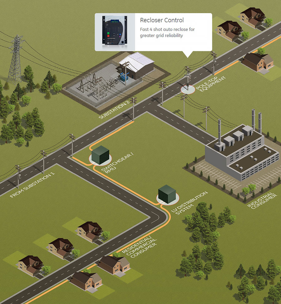
The recloser must have an accurate and efficient tripping mechanism to clear as many faults as possible and fulfill its primary function. The R650 contains a unique driving electronics module that has been specifically matched to the G&W Viper-ST recloser device. This design provides reliable 4 shot auto reclosing. Supported modes of operation include:
When lockout occurs the recloser becomes a pivotal fault make and fault break switch. The optimization of the network is now in the hands of the operator, either manually or automatically through automation and/or FDIR/ FLISR schemes. Whichever scheme is employed, reliable communications and rapid response is required.
The R650 supports redundant Ethernet and fiber port physical interface options and a wide range of industry standard protocols for communication, namely Modbus TCP/IP, DNP 3.0, IEC 60870-5-101, IEC 60870-5-103, IEC 60870-5-104, IEC 61850 ED2, IEC 62439 / PRP/HSR.
The Multilin R650 offers a complete range of standard and advanced protection elements with multiple stages and wide setting ranges. The recloser controller provides comprehensive directional and non-directional overcurrent protection, along with optional single phase tripping and reclosing to limit system impact and improve reliability. A synchronism check function ensures that the voltages are within safe limits before allowing manual closing and auto reclose operations. Additionally, voltage and frequency protection elements may be used to disconnect generation connected to the feeder. The R650 includes six voltage inputs to monitor voltages on both sides of the recloser thereby delivering a safer level of performance.
Driving Electronics Module
At the heart of the R650 design is the driving electronics module that accurately matches the requirements of the recloser device with the controller outputs. This module ensures minimum delay between the R650 output signals and the breaker operation. Through intelligent design, this reliable performance is achieved utilizing minimal power, providing operators with true multiple shot capability.
The driving electronics module design has been extensively tested and validated to ensure optimum performance and facilitate high-speed, multi-shot capability. Test results indicate that the module enables the trip capacitors to maintain sufficient charge voltage to perform 4 cycles of close and trip fast.
Functional Block Diagram
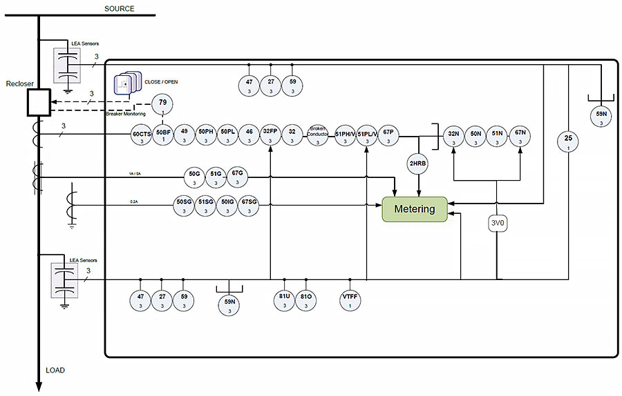
ANSI Device Numbers and Functions
| Device Number | Function |
|---|---|
| 25 | Synchronism Check |
| 27 | Source/Load Undervoltage |
| 32 | Sensitive Directional Power |
| 32FP | Forward Power |
| 32N | Wattmetric Zero-Sequence Directional |
| 46 | Negative Sequence Time Overcurrent |
| 47 | Negative Sequence Voltage |
| 49P | Thermal Model |
| 50BF | Breaker Failure |
| 50PH/PL | Phase Instantaneous Overcurrent (High/Low) |
| 50N | Neutral Instantaneous Overcurrent |
| Device Number | Function |
|---|---|
| 50G | Ground Instantaneous Overcurrent |
| 50SG | Ground Instantaneous Overcurrent for sensitive ground systems (measured from 5th current transformer input) |
| 50IG | Isolated Ground Instantaneous Overcurrent (measured from 5th current transformer input) |
| 51N | Neutral Time Overcurrent |
| 51G | Ground Time Overcurrent |
| 51SG | Sensitive Ground Time Overcurrent |
| 51PH/V | Voltage Restraint Phase Time Overcurrent (high) |
| 51PL/V | Voltage Restraint Phase Time Overcurrent (low) |
| 59 | Source/Load Overvoltage |
| Device Number | Function |
|---|---|
| 59N | Source/Load Neutral Overvoltage |
| 67P | Phase Directional Overcurrent |
| 67N | Neutral Directional Overcurrent |
| 67SG | Sensitive Ground Directional Overcurrent |
| 79 | Autoreclose (Four shot recloser) |
| 81 U/O | Under/Over Frequency |
| - | Broken Conductor |
| VTFF | VT Fuse Failure Detection |
| 60CTS Failure | Current Transformer Failure |
| 2nd Harmonic Inhibit | Second Harmonic Inhibit |
From simple automation to advanced analytics, the R650 provides the flexibility and scalability required to meet unique application requirements.
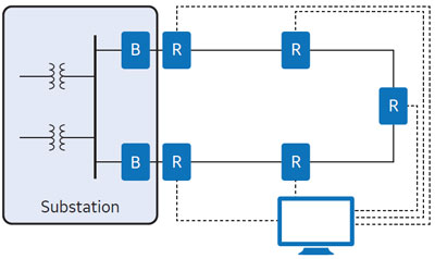
Simple loop recloser automation schemes
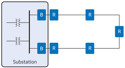 Simple Loop Automation
This is a logic-based automation scheme for self-healing networks. This type of scheme is generally used for providing faster fault isolation and restoration.
Individual recloser controllers make decisions for restoration based on the restoration logic that is programmed into the controllers. This results in quick isolation of the faulty section and automatic restoration thereby minimizing impact on other neighboring customers.
Advanced loop recloser automation schemes
The recloser controllers can provide data to remote SCADA, Outage Management Systems (OMS) and Distribution Management Systems (DMS). These systems manage the network automation process by utilizing the recloser controller data for running FDIR/FLISR and taking restoration decisions dynamically.
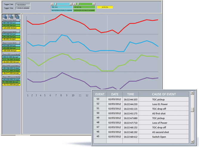
The EnerVista™ Suite is an industry-leading set of software programs that simplifies every aspect of using the R650. The EnerVista suite provides all the tools to monitor the status of the recloser, maintain the controller, and integrate information measured by the R650 into DCS or SCADA monitoring systems.
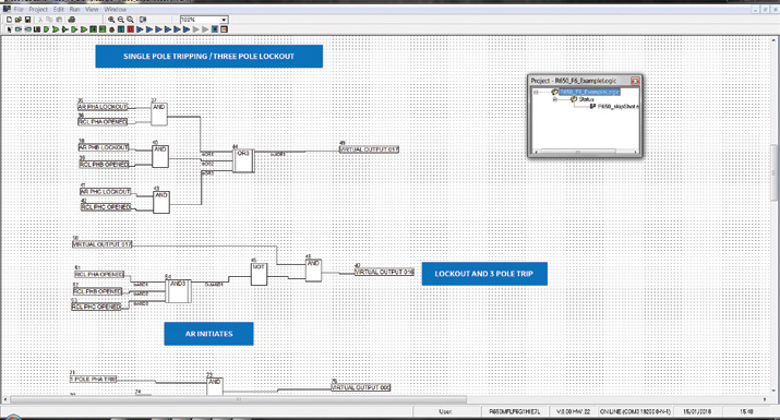
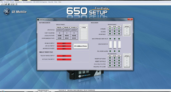
Examples of Graphical Logic Capability and Asset Monitoring Dashboard
GE Vernova offers an industry-leading suite of controllers that support a variety of...
View MoreManufacturing for this product has been discontinued.
Manufacturing for this product has been discontinued.
GE Vernova offers an industry-leading suite of controllers that support a variety of...
View MoreManufacturing for the product has been discontinued. As an alternative please refer to the Reason H49 PRP/HSR Redbox Switch.
The DS Agile H38 is a range of standalone Ethernet switches compliant with the IEC 62439-3 Clause-4 PRP protocol, providing redundant, inter-operable, data communication. This redundancy box – ‘RedBox’- also supports the Precision Time Protocol (PTP) according to IEEE 1588 v2, to deliver precise local time synchronization to the IRIG-B port.
Manufacturing for the product has been discontinued. As an alternative please refer to the Reason H49 PRP/HSR Redbox Switch.
The DS Agile H38 is a range of standalone Ethernet switches compliant with the IEC 62439-3 Clause-4 PRP protocol, providing redundant, inter-operable, data communication. This redundancy box – ‘RedBox’- also supports the Precision Time Protocol (PTP) according to IEEE 1588 v2, to deliver precise local time synchronization to the IRIG-B port.
GE Vernova offers an industry-leading suite of controllers that support a variety of...
View MoreThe MCP is a microprocessor based digital relay system that provides protection, control and monitoring functions for medium voltage capacitor banks.
• Instantaneous overcurrent
• Time overcurrent
• Neutral overcurrent or overvoltage
• Instantaneous overvoltage
• Time overvoltage
• Local and remote breaker operation<
• Metering: current and voltage
• Breaker supervision
• Event record of last 255 events
The MCP is a microprocessor based digital relay system that provides protection, control and monitoring functions for medium voltage capacitor banks.
• Instantaneous overcurrent
• Time overcurrent
• Neutral overcurrent or overvoltage
• Instantaneous overvoltage
• Time overvoltage
• Local and remote breaker operation<
• Metering: current and voltage
• Breaker supervision
• Event record of last 255 events
GE Vernova offers an industry-leading suite of controllers that support a variety of...
View MoreManufacturing for this product has been discontinued. Please contact us to discuss alternatives.
Manufacturing for this product has been discontinued. Please contact us to discuss alternatives.
Auto/Manual or Local/Remote control
Adjustable Voltage Bandwidth
Configurable Voltage ratio correction
Tap change time delay
Voltage runback limits
3 stage Voltage reduction
Line Drop Compensation
(forward & reverse)
Reverse Power Operation & Override
Tap change inhibits
Tap position limits
Sequential and non-sequential type
Bi-directional mode of operation
Drag hands operation
3 setting groups

Voltage regulator controllers and Capacitor bank controllers can operate as part of an integrated Volt/VAR Control (IVVC) scheme or as a Centralized Volt/VAR control (CVVC) system. The IVVC or CVVC system works to achieve two key objectives:
Optimize Voltage - through ‘Conservation of Voltage’ that leads to reduced demand, that may result in decreased generation up to 6%.
Increased efficiency- through improved power factor and reduced VAR which helps to reduce power line losses.
Based on GE Vernova’s proven controller platform with tens of thousands of units installed globally, the Multilin Voltage Regulator Controller underwent extensive Accelerated Life Testing (ALT) and Highly Accelerated Life Testing (HALT) to validate accurate functionality under specified conditions and to ensure accurate performance in extreme operating conditions and harsh environments.
To provide optimal application flexibility, the Multilin Voltage Regulator Controller offers two modes or methods of operation in which the device can be implemented to control the voltage regulator: a) Manual Mode (Local Control or Remote Control). b) Automatic Mode
In this mode, it is possible to Raise or Lower the tap locally from the Push buttons that are available on the front panel of the Multilin Voltage Regulator Controller. For added operational reliability and operator safety, inhibit functions configured in the unit continue to operate as defined.
In this mode, the commands for Tap Raise and Lower are received from SCADA or the Integrated Volt/VAR systems via communications. This communications channel can be provided via optional radio or cellular communications.
In automatic mode, the Multilin Voltage Regulator Controller compares the measured voltage to the set voltage level, and if the difference exceeds the set bandwidth (voltage limits), the Multilin Voltage Regulator Controller issues a Raise or Lower tap commands to maintain the desired voltage levels.
Voltage Level (Bandcenter)
Voltage Bandwidth
Voltage Reduction
Computation Time Delay
Line Drop Compensation (LDC)
Reverse Power LDC
Reverse Power
Reverse Power Override
Voltage Runback Limits
Inhibit Operations
Overcurrent Inhibit
Overvoltage Inhibit
Under-Voltage Inhibit
Multiple setpoint groups
Expandable inputs and outputs for advanced applications
Customized automation schemes using FlexLogic™
The Multilin Voltage Regulator Controller offers powerful I/O and programmable logic (FlexLogic™) options for advanced automation control, reducing the need and costs associated with additional programmable controllers or discrete control devices.
The Multilin Voltage Regulator Controller has three identical set point groups. The activation of the group can be done either from the HMI or via a Digital Input.
The Multilin Voltage Regulator Controller provides 32 virtual inputs and 32 virtual outputs that provide users the ability to send commands to the device. The Multilin Voltage Regulator Controller can accept commands from SCADA, through the front HMI, or front USB port to issue commands such as Raise or Lower tap position.
The Multilin Voltage Regulator Controller has the ability to force commands from the menu structure. This can also be achieved via the EnerVista software that runs on a PC. This simulation ensures that the Raise and Lower commands can be safely issued from a distance without using the HMI.
The Drag – Hand Reset provides the ability to reset the Drag hands to the current tap position. Commands can be sent to the Multilin Voltage Regulator Controller to reset the Drag Hand position from the front HMI , from SCADA or through the front panel USB communications.
FlexLogic in the Multilin Voltage Regulator Controller, provides the ability to create customized control schemes. This minimizes the need and costs associated with auxiliary components and wiring.

Metering - current, voltage, power, frequency, PF, Harmonics
Event Recorder - Up to 256 time tagged events
Enhanced system diagnostics & reporting
The Multilin Voltage Regulator Controller provides high accuracy metering and recording of AC signals. The following are the parameters that are metered by the Multilin Voltage Regulator Controller
Phase-Ground Voltages (kV)
Phase to phase Voltages (kV)
Line Voltage (kV)
Phase A, B, and C currents (A)
Line Current (A)
Ground Current (A)
3-Phase Active power (KW)
3-Phase Reactive power (KVar)
3-Phase Apparent Power
Power Factor (Lag or Lead)
2nd to 8th harmonic up to 20% – for current
2nd to 8th harmonic up to 20% – for voltage
THD in 20% – for current
THD in 20% – for voltage
These metering data can be easily integrated with a customers’ database and can also be easily viewed in their SCADA or DMS system.
To significantly reduce time and enable more effective disturbance, post fault analysis and troubleshooting, the Multilin Voltage Regulator Controller provides an integrated event recorder and detailed diagnostic features.
The advanced disturbance diagnostic features included in the Multilin Voltage Regulator Controller includes recording functions through an enhanced Data Logger with 10 channel RMS recorder, statistics & counters.
Multilin Voltage Regulator Controller includes two tap changer counters which records the following information:
DAILY TAP OPERATIONS
TOTAL TAP OPERATIONS
The MIN/MAX TAP in the Multilin Voltage Regulator Controller provides information on the lowest (minimum), and the highest (maximum) tap position the tap changer reached during one 24 hour day period.
A comprehensive device health diagnostic test is performed by the Multilin Voltage Regulator Controller during startup and continuously at runtime to test its own major functions and critical hardware. These diagnostic tests monitor for conditions that could impact the Multilin Voltage Regulator Controller’s performance, evaluate the criticality of this impact and present device status via SCADA communications and front panel display.


Front panel quick keys provides direct access to key individual setting parameters

4-Level device security to maintain authorized access only
Simplified device configuration software tool and industry leading suite of software tools to manage and maintain Multilin devices.
The Multilin Voltage Regulator Controller and associated software tools provide a suite of security features that ensure only approved personnel can make changes to the device configuration or execute operational commands.
The Multilin Voltage Regulator Controller offers multiple levels of password security to limit access control based on settings or command levels. There are four levels of password security provided:
Local Settings Access
Local Control Access
Remote Settings Access
Remote Control Access
Local Access refers to users making changes using the front USB serial port and the HMI. Remote Access refers to users making changes using the rear RS485 port.
The EnerVista™ Suite is an industry-leading set of software programs that simplifies every aspect of using the Multilin Voltage Regulator Controller. The EnerVista™ suite provides all the tools to monitor the status of the protected asset, maintain the controller, and integrate information measured by the Multilin Voltage Regulator Controller into SCADA or the DMS monitoring systems. The ability to easily view sequence of events is an integral part of the setup software, as postmortem event analysis is critical to proper system operation.
Learn More![]()

GE Vernova offers an industry-leading suite of controllers that support a variety of...
View MoreManufacturing for this product has been discontinued. Please contact us if you have any inquiries.
Manufacturing for this product has been discontinued. Please contact us if you have any inquiries.
Auto/manual or Local/Remote
Cold Load Pickup
Phase IOC detection
Phase TOC detection
Neutral TOC detection
Over Voltage
Under Voltage
Voltage Unbalance
Power loss
Reverse power
A key driver and measurement of utility effectiveness is in the reliability of power to its customers. As many faults on overhead distribution lines are transient in nature, reclosing at the substation and installation of mid-line reclosers./switches can improve a utilities SAIDI reliability index by up to 24%.
When permanent faults occur on overhead lines, having feeders with increasing degrees or automation can greatly enhance distribution grid reliability and reduce restoration of unfaulted segments from several hours to a few seconds or minutes. A key component of these automation schemes is intelligent controllers that can integrate with FDIR systems through sharing local information and accepting control commands.
Robust Design
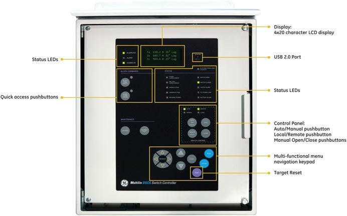
Based on GE Vernova's proven controller platform with tens of thousands of units installed globally, the Multilin DGCS undergoes extensive Accelerated Life Testing (ALT) and Highly Accelerated Life Testing (HALT) to validate accurate functionality under specified conditions and to ensure accurate performance in extreme operating conditions and harsh environments.
The Multilin DGCS Switch controller provides two modes of operation:
Remote mode
Local mode
The Multilin DGCS switch controller measures three phase voltages and currents, and based on the measurements, manages Auto-Sectionalizing functionality:
Multiple setpoint groups
Expandable inputs and outputs for advanced applications
Customized automation schemes using FlexLogic™
The Multilin DGCS offers powerful I/O and programmable logic (FlexLogic™) options for advanced automation and control, reducing the need and costs associated with additional programmable controllers or discrete control devices.
For both operational efficiency and reliability reasons, the Multilin DGCS provides remote control for operating switchgear. The Multilin DGCS is capable of providing both local and manual control of the switchgear.
The Multilin DGCS has three identical set point groups. The activation of the group can be done either from the HMI or via a digital input.
The Multilin DGCS provides 32 virtual inputs and 32 virtual outputs that provide users with the ability to send commands to the device. The Multilin DGCS can accept commands from SCADA, through the front HMI, or front USB port to issue commands such as close or open.
The Multilin DGCS has the ability to force commands from the menu structure. This can also be achieved via the EnerVista™ software that runs on a PC. This simulation ensures that the close and open commands can be safely issued from a distance without using the HMI.
FlexLogic in the Multilin DGCS provides the ability to create customized control schemes. This minimizes the need and costs associated with auxiliary components and wiring
Metering - current, voltage, power, energy, frequency, PF, Harmonics
Event Recorder - Up to 256 time tagged events
Statistics & counters
Enhanced system diagnostics & reporting
The Multilin DGCS provides high accuracy metering and recording of all AC signals, measuring the following key parameters:
Phase-Ground Voltages (kV)
Phase to phase Voltages (kV)
Positive, Negative, Zero Sequence Voltage
Phase A, B, and C currents (A)
Positive, Negative, Zero Sequence Current Ground Current (A)
3-Phase Active power (KW)
3-Phase Reactive power (KVar)
3-Phase Apparent Power
Power Factor (Lag or Lead)
Pos. & Neg. (Import & Export) Real Energy (kWh)
Pos. & Neg. (Import & Export) Reactive Energy (kVarh)
2nd to 8th harmonic up to 20% – for current
2nd to 8th harmonic up to 20% – for voltage
THD in 20% – for current
THD in 20% – for voltage
These data points can be easily integrated into a customer's database for seamless viewing through a SCADA or DMS system like GE Vernova's PowerOn or GeNe.
Trip Counter
Open Counter
Close Counter
KI²t Phase A Counter
KI²t Phase B Counter
KI²t Phase C Counter
Total Close/Open Operation
The maintenance elements in the Multilin DGCS provides alarms to the system based on the maximum number of closing/opening executed commands per period of time and I²t measurements per feeder.
he Multilin DGCS provides an integrated event recorder and detailed diagnostic features. The sequence of events recorder offers the following features:
Up to 256 consecutive events stored
Enable or disable, operate and dropout events by set points
Phase voltage/current and power metering shot is also included and stored at each event
Comprehensive device health diagnostic tests are performed by the Multilin DGCS during startup and continuously at runtime to test its own major functions and critical hardware User Interface.
4-Level device security to maintain authorized access only
Simplified device configuration software tool and industry leading suite of software tools to manage and maintain Multilin devices.
The DGCS and associated software tools provide a suite of security features that ensure only approved personnel can make changes to the device configuration or execute operational commands.
The DGCS offers multiple levels of password security to limit access control based on settings or command levels. There are four levels of password security provided:
Local Settings Access
Local Control Access
Remote Settings Access
Remote Control Access
Local Access refers to users making changes using the front USB serial port and the HMI. Remote Access refers to users making changes using the rear RS485 port.
The EnerVista™ Suite is an industry-leading set of software programs that simplifies every aspect of using the DGCS Voltage Regulator Controller. The EnerVista™ suite provides all the tools to monitor the status of the protected asset, maintain the controller, and integrate information measured by the DGCS into SCADA or the DMS monitoring systems. The ability to easily view sequence of events is an integral part of the setup software, as postmortem event analysis is critical to proper system operation.
Learn More![]()
GE Vernova offers an industry-leading suite of controllers that support a variety of...
View MoreManufacturing for this product has been discontinued. Please contact us to discuss alternatives.
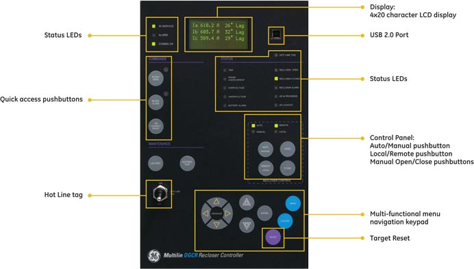
The Multilin DGCR is an advanced Controller for detection of faults and controlling overhead reclosers. The Multilin DGCR is compatible with many traditional and magnetic actuator reclosers and provides a great degree of flexibility in integrating with FDIR systems.
Manufacturing for this product has been discontinued. Please contact us to discuss alternatives.
The Multilin DGCR is an advanced Controller for detection of faults and controlling overhead reclosers. The Multilin DGCR is compatible with many traditional and magnetic actuator reclosers and provides a great degree of flexibility in integrating with FDIR systems.
A key driver and measurement of utility effectiveness is in the reliability of power to its customers. As many faults on overhead distribution lines are transient in nature, reclosing at the substation and installation of mid-line reclosers./switches can improve a utilities SAIDI reliability index by up to 24%.
When permanent faults occur on overhead lines, having feeders with increasing degrees or automation can greatly enhance distribution grid reliability and reduce restoration of unfaulted segments from several hours to a few seconds or minutes. A key component of these automation schemes is intelligent controllers that can integrate with FDIR systems through sharing local information and accepting control commands.
Robust Design
Based on GE Vernova's proven controller platform with tens of thousands of units installed globally, the Multilin DGCR undergoes extensive Accelerated Life Testing (ALT) and Highly Accelerated Life Testing (HALT) to validate accurate functionality under specified conditions and to ensure accurate performance in extreme operating conditions and harsh environments.
The Multilin DGCR Recloser controller provides two modes of operation:
The Multilin DGCR recloser controller measures three phase voltages and currents, and based on the measurements, manages Auto-Recloser functionality:
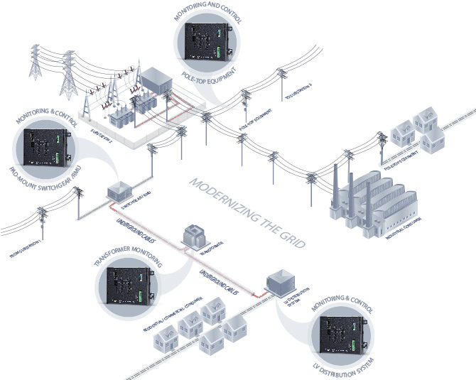
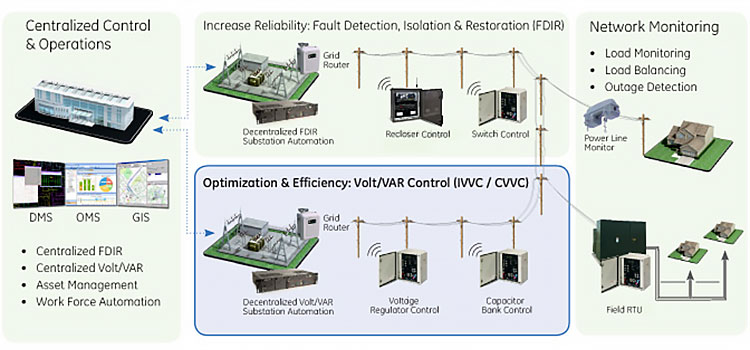 Above depicts a simplified distribution network and two key distribution automation solutions driving grid optimization, efficiency and reliability
The Multilin DGCR offers powerful I/O and programmable logic (FlexLogic™) options for advanced automation and control, reducing the need and costs associated with additional programmable controllers or discrete control devices.
For both operational efficiency and reliability reasons, the Multilin DGCR provides remote control for operating switchgear. The Multilin DGCR is capable of providing both local and manual control of the switchgear.
The Multilin DGCR has three identical set point groups. The activation of the group can be done either from the HMI or via a digital input.
The Multilin DGCR provides 32 virtual inputs and 32 virtual outputs that provide users with the ability to send commands to the device. The Multilin DGCR can accept commands from SCADA, through the front HMI, or front USB port to issue commands such as close or open.
The Multilin DGCR has the ability to force commands from the menu structure. This can also be achieved via the EnerVista™ software that runs on a PC. This simulation ensures that the close and open commands can be safely issued from a distance without using the HMI.
FlexLogic in the Multilin DGCR provides the ability to create customized control schemes. This minimizes the need and costs associated with auxiliary components and wiring.
The Multilin DGCR provides high accuracy metering and recording of all AC signals, measuring the following key parameters:
These data points can be easily integrated into a customer's database for seamless viewing through a SCADA or DMS system like GE Vernova's PowerOn or GeNe.
The maintenance elements in the Multilin DGCR provides alarms to the system based on the maximum number of closing/opening executed commands per period of time and I²t measurements per feeder.
The Multilin DGCR provides an integrated event recorder and detailed diagnostic features. The sequence of events recorder offers the following features:
Comprehensive device health diagnostic tests are performed by the Multilin DGCR during startup and continuously at runtime to test its own major functions and critical hardware User Interface.
The DGCR and associated software tools provide a suite of security features that ensure only approved personnel can make changes to the device configuration or execute operational commands.
The DGCR offers multiple levels of password security to limit access control based on settings or command levels. There are four levels of password security provided:
Local Access refers to users making changes using the front USB serial port and the HMI. Remote Access refers to users making changes using the rear RS485 port.
The EnerVista™ Suite is an industry-leading set of software programs that simplifies every aspect of using the DGCR Voltage Regulator Conroller. The EnerVista™ suite provides all the tools to monitor the status of the protected asset, maintain the controller, and integrate information measured by the DGCR into SCADA or the DMS monitoring systems. The ability to easily view sequence of events is an integral part of the setup software, as postmortem event analysis is critical to proper system operation. Learn More
GE Vernova offers an industry-leading suite of controllers that support a variety of...
View MoreManufacturing for this product has been discontinued. As an alternative, please refer to the iBox.
Manufacturing for this product has been discontinued. As an alternative, please refer to the iBox.
Effective fault isolation is a key feature for grid reliability. The Multilin DGCM provides early warning for downstream overcurrent and earth faults. It can be programmed to isolate a faulted segment, either independently or from the remote. The Multilin DGCM also offers control, monitoring and diagnostics in one integrated, efficient design.
Instantaneous and time overcurrent functions are available for phase, neutral and negative sequence currents. A variety of time curves are provided, including IEEE/ANSI, IEC A/B/C/long time inverse/short time inverse, definite time and user-programmable curves.
The Multilin DGCM can be programmed to block instantaneous overcurrent elements, and raise the pickup time of overcurrent elements, when a cold load condition is detected. The cold load condition is detected during the closing of the breaker on a feeder that has been de-energized for a long time. The feeder inrush and motor accelerating currents during breaker closing may be above some overcurrent protection settings.
The phase OV protection guards voltage sensitive feeder loads and circuits against sustained OV conditions. It generates alarms when the voltage exceeds the selected voltage level for the specified time delay.
The phase UV detection alerts utilities against sustained UV conditions. The UV detector generates an alarm when the voltage drops below the selected voltage level after a specified time delay.
The Multilin DGCM can detect a power loss condition in each phase of the power distribution line. Open/close commands are blocked, unless currents and voltages of each phase fall below minimum set values.
The Multilin DGCM provides high accuracy metering and recording of all AC signals, measuring the following key parameters:
To enable more effective distribution, post fault analysis and troubleshooting, the Multilin DGCM provides an integrated event recorder and detailed diagnostic features. The event recorder offers:
• Storage for up to 1024 consecutive events
The Multilin DGCM provides a 200 channel RMS recorder for advanced disturbance diagnostic features.
The Multilin DGCM data logger helps in better understanding the analog channel behavior, by sampling at a selectable time interval rate of 1 to 60 minutes.
 The Multilin DGCM event recorder enables users to analyze the sequence of events . Each event is stored with the event number, date, time and analog data of interest.
The Multilin DGCM utilizes industry standard communications technologies, making it one of easiest and flexible controllers to use and integrate into new and existing SCADA or DMS infrastructures.
Multiple communication ports and protocols allow for remote control and easy access to device and system information. All communication ports are capable of simultaneous communications.
Simultaneous industry standard protocols supported:
The Multilin DGCM’s integrated cellular modem eliminates the need for external wireless devices, which reduces infrastructure costs.
Several options for MDS™ radios when purchased with enclosure:

The EnerVista Suite is an industry-leading set of software programs that simplifies every aspect of using the Multilin DGCM. EnerVista provides the tools to monitor the status of the protected asset, maintain the controller and integrate information measured by the Multilin DGCM into SCADA or DMS monitoring systems.
EnerVista Launchpad is a powerful software package that provides users with of the setup and support tools needed for configuring and maintaining GE Vernova’s Multilin products. The setup software within Launchpad allows the configuration of devices in real-time, by communicating via serial, Ethernet or modem connections, or offline, by creating device setting files to be sent to devices at a later time.

GE Vernova offers an industry-leading suite of controllers that support a variety of...
View MoreManufacturing for this product has been discontinued. Please contact us if you have any inquiries.
Manufacturing for this product has been discontinued. Please contact us if you have any inquiries.

Voltage regulator controllers and Capacitor bank controllers can operate as part of an integrated Volt/VAR Control (IVVC) scheme or as a Centralized Volt/VAR control (CVVC) system. The IVVC or CVVC system works to achieve two key objectives:
Optimize Voltage - through ‘Conservation of Voltage’ that leads to reduced demand, that may result in decreased generation up to 6%.
Increased efficiency- through improved power factor and reduced VAR which helps to reduce power line losses.
Robust Design
As a complete package, the Multilin Capacitor Bank Controller is offered in a NEMA-4 certified cabinet that is suitable for operation of harsh environments with an operating range of -40°C to + 60°C (-40°F to +140°F).
Mode of Operation
To provide optimal application flexibility, the Multilin Capacitor Bank Controller offers two modes or methods of operation in which the device can be implemented to control the Capacitor Bank:a) Manual Mode (Local Control or Remote Control). b) Automatic Mode
Manual Mode – Local Control
In this mode, it is possible to Open or Close the Capacitor Bank, locally, from the large pushbuttons located on the front panel of the Multilin Capacitor Bank Controller. For increased operational reliability and operator safety, inhibit functions configured in the unit will continue to operate as defined.
Manual Mode – Remote Control
In this mode, the commands for Open or Close of the Capacitor Bank are received via communication channels from the SCADA or an integrated Volt/VAR system. This communication channel can be provided via optional radio or cellular communications.
Automatic Mode
In automatic mode, the Multilin Capacitor Bank Controller issues commands to Open or Close the Capacitor Bank. In this mode, the Capacitor Bank is controlled
Key Capacitor Bank Control Features:
Reverse Power Detection
The Multilin Capacitor Bank Controller includes a Reverse Power Detection function, which defines the minimum pickup required to detect reverse power conditions.
Neutral Overcurrent Protection (Blown Fuse Condition)
In situations where the capacitor bank has been tripped due to a neutral current unbalance situation, the Multilin Capacitor Bank Controller will execute a reclose action to validate the state of the fault, ensuring the fault was not transient in nature. This automatic reclose action ensures maximizes system reliability.
The Multilin Capacitor Bank Controller offers powerful I/O and programmable FlexLogic™ options for advanced automation control, reducing the need for additional programmable controllers or discrete control relays. The Multilin Capacitor Bank Controller has three identical set point groups. The activation of the group can be done either from the HMI or via a Digital Input.
Set point group control
The Multilin Capacitor Bank Controller has three identical set point groups. The activation of the group can be done either from the HMI or via a Digital Input.
Virtual Inputs and Outputs
The Multilin Capacitor Bank Controller provides 32 virtual inputs and 32 virtual outputs that provide users the ability to send commands to the device. The Multilin Capacitor Bank Controller can accept commands from SCADA, through the front HMI, or front USB port to issue commands such as Open or Close.
Command Setting
The Multilin Capacitor Bank Controller has the ability to force commands from the menu structure accessible through the Multilin EnerVista setup software that runs on a PC.
FlexLogic™
Advanced FlexLogic in the Multilin Capacitor Bank Controller provides the ability to create customized control schemes. This minimizes the need for auxiliary components and wiring, thus reducing complexity and costs.

The Multilin Capacitor Bank Controller provides high accuracy metering and recording of AC signals, measuring the following key parameters:
These data points can be easily integrated into a customer’s database for seamless viewing through a SCADA or DMS system.
The Multilin Capacitor Bank Controller has the ability to monitor the following setpoints / conditions and issue an alarm if measured values fall outside of specified limits:
Event recorder
To significantly reduce time and enable more effective disturbance, post fault analysis and troubleshooting, the Multilin Capacitor Bank Controller provides an integrated event recorder and detailed diagnostic features.
Data Management and Diagnostics
The Multilin Capacitor Bank Controller provides advanced disturbance diagnostic features that significantly reduce the time and costs associated with troubleshooting power system events and reconstruction. Recording functions include enhanced diagnostics with a 10 channel RMS recorder Data Logger.
Statistics & Counters
The Multilin Capacitor Bank Controller provides counters which records key operational parameters to aid in enabling preventative maintenance programs. The Multilin Capacitor Bank Controller includes many counters & statistical values.
Advanced Device Health Diagnostics
Comprehensive device health diagnostic tests are performed by the Multilin Capacitor Bank Controller during startup and continuously at runtime to test its own major functions and critical hardware. These diagnostic tests monitor for conditions that could impact the Multilin Capacitor Bank Controller’s performance, evaluates the potential impact and criticality of this condition and presents the device status to operators, via SCADA and/or through the front panel display.

The Multilin Capacitor Bank Controller utilizes industry standard, communications technologies making it one of easiest and most flexible controllers to use and integrate into new and existing SCADA or DMS infrastructures. Supported communication protocols include:
Multiple communication ports and protocols allow for remote control and easy access to device and system information. All communication ports are capable of simultaneous communications. The Multilin Capacitor Bank Controller can also communicate to Volt/VAR or SCADA systems via wireless communications media. The supported wireless media includes:

Front Penel quick keys provides direct access to key individual setting parameters

4-Level device security to maintain authorized access only
Simplified device configuration software tool and industry leading suite of software tools to manage and maintain Multilin devices.
The Multilin Capacitor Bank Controller and associated software tools provide a suite of security features that ensure only approved personnel can make changes to the configuration of the system or execute commands. These functions enable a utility to meet NERC/CIP requirements.
Password Security
The Multilin Capacitor Bank Controller offers multiple levels of password security to limit access control based on settings or command levels. There are four levels of password security provided:
Local Access refers to users making changes using the front USB serial port and the HMI. Remote Access refers to users making changes using the rear RS485 port.
The EnerVista™ Suite is an industry-leading set of software programs that simplifies every aspect of using the Multilin Capacitor Bank Controller The EnerVista™ suite provides all the tools to monitor the status of the protected asset, maintain the controller, and integrate information measured by the DGCC into SCADA or the DMS monitoring systems. The ability to easily view sequence of events is an integral part of the setup software, as postmortem event analysis is critical to proper system operation.
Learn More![]()

GE Vernova offers an industry-leading suite of controllers that support a variety of...
View More