Has legacy products
On
The F60, a member of the UR Family of protection relays, provides high performance feeder protection, control, monitoring and metering in an integrated, economical, and compact package. The F60 includes GE Vernova Multilin’s unique high-impedance fault detection for fast and reliable detection of downed conductors.
The F60, a member of the UR Family of protection relays, provides high performance feeder protection, control, monitoring and metering in an integrated, economical, and compact package. The F60 includes GE Vernova Multilin’s unique high-impedance fault detection for fast and reliable detection of downed conductors.

New and Enhanced Communication Capabilities

Cyber Security - CyberSentry UR (FW v7.xx)
CyberSentryTM enables UR devices to deliver full cyber security features that help customers to comply with cyber security requirements (NERC CIP, IEEE 1686, IEC 62443, etc):

Fully Compatible with IEC 61850-9-2LE or IEC61869 process bus schemes:

Extended Oscillography Records (FW v7.xx)

New and Enhanced Protection and Control Functionality
The F60 feeder protection system provides feeder protection, control, monitoring and metering in an integrated, economical, and compact package. As part of the Universal Relay (UR) Family, the F60 features high performance protection, expandable I/O options, integrated monitoring and metering, high-speed communications, and extensive programming and configuration capabilities. The F60 incorporates a unique and matured algorithm to detect high-impedance faults such as downed conductor detection. It also provides fast and deterministic execution of programmable logic necessary for substation automation applications. Graphical programming tools (Viewpoint Engineer), supported by a library of logic components, make the F60 simple to use and configure. The F60 has a wide range of protection elements that have many years of proven field experience.
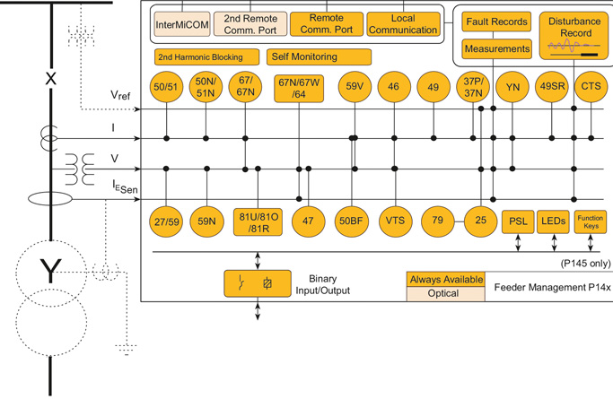
Functional Block Diagram
ANSI® Device Numbers & Functions
|
|
|
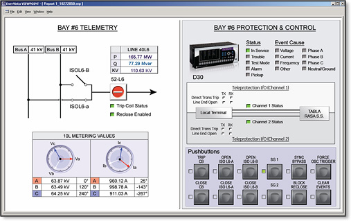 The D30 is the single point for protection, control, metering, and monitoring in one integrated device that can be easily connected directly to HMI or SCADA monitoring and control systems.
Advanced Automation
The D30 incorporates advanced automation features including powerful FlexLogic™ programmable logic, communication, and SCADA capabilities that far surpass what is found in the average line protection relay used for subtransmission. The D30 integrates seamlessly with other UR relays for complete system protection.
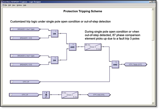 FlexLogic™ allows for the customization of D30 for custom protection, control and automation, allowing users to build line protection schemes and applications for their equipment.
Complete IEC 61850 Process Bus solution providing resource optimization and minimizing total P & C life cycle costs
The F60 provides advanced communications technologies for remote data and engineering access, making it easy and flexible to use and integrate into new and existing infrastructures. Direct support for fiber optic Ethernet provides high-bandwidth communications allowing for low-latency controls and high-speed file transfers of relay fault and event record information. The available three independent and redundant Ethernet options provide the means to create fault tolerant communication architectures in an easy, cost-effective manner.
The F60 supports the most popular industry standard protocols enabling easy, direct integration into monitoring and SCADA systems.
Use the F60 with integrated IEC 61850 to lower costs associated with feeder protection, control and automation. GE Vernova’s leadership in IEC 61850 comes from thousands of installed devices and follows on years of development experience with UCA 2.0.
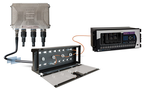
The F60’s IEC 61850 Process Bus module is designed to interface with the Multilin HardFiber System, allowing bi-directional IEC 61850 fiber optic communications. The HardFiber System is designed to integrate seamlessly with existing Universal Relay applications, including protection functions, FlexLogic, metering and communications.
The F60 can also connect to GE Vernova MU320 or third-party merging units using standard IEC 61869 or IEC 61850-9-2LE communication protocols.
CyberSentry enables UR devices to deliver full cyber security features that help customers to comply with NERC CIP and NITIR 7628 cyber security requirements through supporting the following core features:
Secure FW upgrade
UR FW files v7.9 and up now include a hash code that allows for authentication prior to being used for upgrading UR devices.
Password Complexity
Supporting up to 20 alpha- numeric or special characters, UR passwords exceed NERC CIP requirements for password complexity. Individual passwords per role are available.
AAA Server Support (Radius)
Enables integration with centrally managed authentication and accounting of all user activities and uses modern industry best practices and standards that meet and exceed NERC CIP requirements for authentication and password management.
Role Based Access Control (RBAC)
Efficiently administrate users and roles within UR devices. The new and advanced access functions allow users to configure up to five roles for up to eight configurable users with independent passwords. The standard “Remote Authentication Dial In User Service” (Radius) is used for authentication.
Event Recorder (Syslog for SEM)
Capture all cyber security related events within a SOE element (login, logout, invalid password attempts, remote/local access, user in session, settings change, FW update, etc), and then serve and classify data by security level using standard Syslog data format. This enables UR devices integration with established SEM (Security Event Management) systems.
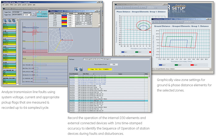
The EnerVista™ suite is an industry-leading set of software programs that simplifies every aspect of using the F60 relay. The EnerVista™ suite provides all the tools to monitor the status of the protected asset, maintain the relay, and integrate information measured by the F60 into DCS or SCADA monitoring systems. Convenient COMTRADE and Sequence of Events viewers are an integral part of the UR setup software included with every UR relay, to carry out postmortem event analysis and ensure proper protection system operation.
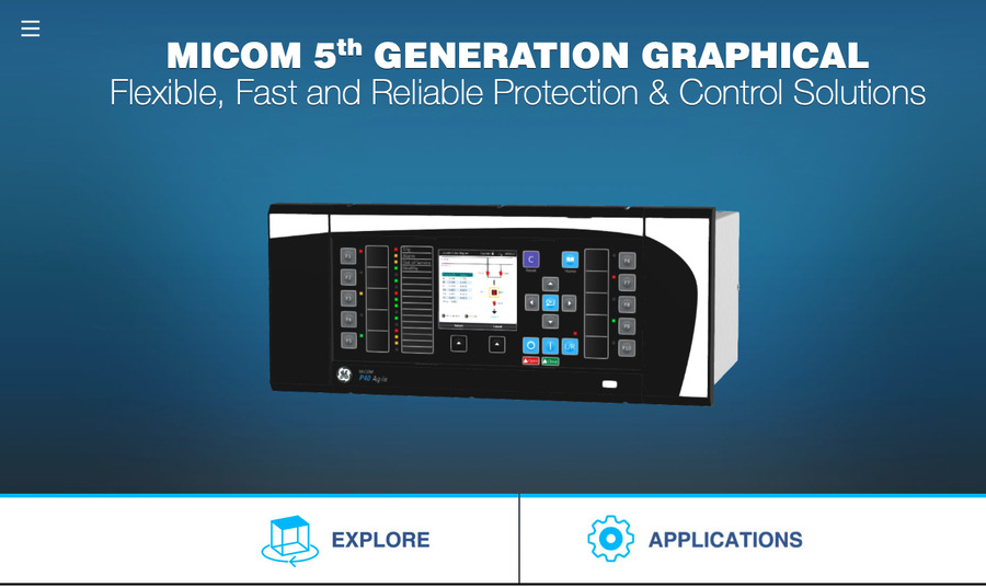
The P84, part of the MiCOM P40 Agile 5th Generation family, is a multi-functional line...
View More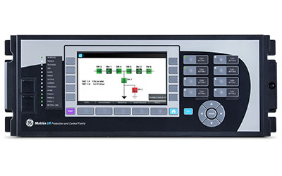
The F60, a member of the UR Family of protection relays, provides high performance feeder...
View More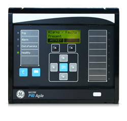
Part of the MiCOM P40 platform, the Agile P14x feeder management relays provide an...
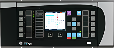
View MoreThe P84, part of the MiCOM P40 Agile 5th Generation family, is a multi-functional line terminal Protection that delivers high performance processing and a graphical HMI as standard. It is ideal for HV, EHV and UHV applications on lines and cables for 1 or 2 breaker applications with patented adaptive auto-reclose functionality.
The P84, part of the MiCOM P40 Agile 5th Generation family, is a multi-functional line terminal Protection that delivers high performance processing and a graphical HMI as standard. It is ideal for HV, EHV and UHV applications on lines and cables for 1 or 2 breaker applications with patented adaptive auto-reclose functionality.
Transmission and distribution systems are essential for the safe, sure routing of power from generation sources to consumers. However, exposed overhead lines transporting power are by nature sometimes vulnerable and prone to fault. In the case of a faulty circuit, the MiCOM range provides speedy protection to trip and isolate it, thereby preventing further damage. Each relay model contains a complete suite of backup protection elements covering all current, voltage and frequency applications. This permits simplified application and spares holdings, because the relay can be adopted as the standard protection platform.
The MiCOM P84 is suitable for feeders controlled by a single circuit breaker and for complex installations where feeders are controlled by two circuit breakers such as ring bus/mesh corner formations and the breaker-and-a-half configurations.
MiCOM Multi-Functional Line Terminal Protection
Buy Now![]()
Key benefits:
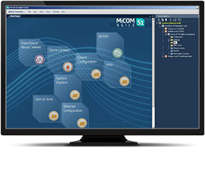
Engineering Tool Suite
S1 Agile is the truly universal PC tool for MiCOM Agile relay, assemble all tools in a palette for simple entry, with intuitive navigation via fewer mouse-clicks. No-longer are separate tools required for redundant Ethernet configuration, phasor measurement unit commissioning, busbar scheme operational dashboards, programmable curve profiles or automatic disturbance record extraction – applications are embedded. MiCOM S1 Agile supports all existing MiCOM, K-Series and Modulex, including a utility for automatic conversion of setting files from previous generations of numerical relays like K-series and MiCOM P20 to the latest P40 Agile models.
To move to the future, with no loss of functionality, no loss of device support, and full compatibility with your installed base and system architecture – request a copy of S1 Agile with the contact form link below.
Key features in the MiCOM S1 family:
MiCOM S1 Agile software request
To receive the MiCOM S1 Agile, please use our Contact form. This will also ensure that you are kept up-to-date with the latest enhancements, including updates and bug fixes.
GE Vernova’s latest P84 MiCOM 5th Generation transmission models offer a perfect functional match to our “mho” family of distance relays, from the heritage installed-base brands GE VERNOVA and Areva. The protection pedigree is maintained, optimised and advanced:
The P84, part of the MiCOM P40 Agile 5th Generation family, is a multi-functional line...
View More
The F60, a member of the UR Family of protection relays, provides high performance feeder...
View More
Part of the MiCOM P40 platform, the Agile P14x feeder management relays provide an...
View MorePart of the MiCOM P40 platform, the Agile P14x feeder management relays provide an integrated solution for the complete protection, control and monitoring of overhead lines and underground cables, covering all distribution and transmission voltage levels. Providing all essential information to efficiently maintain complex power systems and their components, the P14x relay family is user-friendly and highly flexible, allowing application on any electrical network.
Part of the MiCOM P40 platform, the Agile P14x feeder management relays provide an integrated solution for the complete protection, control and monitoring of overhead lines and underground cables, covering all distribution and transmission voltage levels. Providing all essential information to efficiently maintain complex power systems and their components, the P14x relay family is user-friendly and highly flexible, allowing application on any electrical network.
| Device Number | Function |
|---|---|
| 25 | Check Synchronising |
| 27 | Phase and Line Undervoltage |
| 32 | Phase Directional Power |
| 37 | Undercurrent |
| 46 | Negative Sequence Overcurrent |
| 47 | Negative Sequence Overvoltage |
| 49 | Thermal Overload |
| 50/27 | Switch-on to Fault |
| 50 | Phase Definitive Time Overcurrent |
| 51 | Phase Inverse-Time Overcurrent |
| 52 | Breaker and Isolator Control |
| 59 | Phase and Line Overvoltage |
| dv/dt | Rate of Change of Voltage |
| 67 | Directional Phase Overcurrent |
| 68 | Inrush Blocking |
| Device Number | Function |
|---|---|
| 79 | Autoreclose |
| 85 | InterMiCOM Teleprotection |
| 86 | Latching/Lockout Contacts |
| 87 | High-Impedance Busbar Differential |
| 21BL | Load Encroachment/Blinder |
| 21FL | Fault Locator |
| 32S | Sensitive Power |
| 46BC | Broken Conductor |
| 49SR | Silicon Rectivier Thermal |
| 50BF | CB Failure |
| 50N | Earth Fault Definitive Time Overcurrent |
| 51N | Neutral/Ground IDMT Overcurrent |
| SEF | Sensitive Earth Fault, I cos and I sin |
| 51R | Voltage Restrained Overcurrent |
| 51V | Voltage Controlled Overcurrent |
| Device Number | Function |
|---|---|
| PSL | Programmable Logic |
| CLP | Cold Load Pick Up |
| 59N | Neutral Voltage Displacement |
| 59S | Busbar Buswire Supervision |
| 64N | Restricted Earth Fault |
| 67N | Directional Neutral/Ground Overcurrent |
| 67W | Wattmetric Earth Fault |
| 81df/dt | Rate of Change Frequency |
| 81O | Overfrequency |
| 81R | Load Restoration |
| 81U | Underfrequency |
| 81V | Undervoltage Blocking |
| CTS | CT Supervision |
| VTS | VT Supervision |
| YN | Neutral Admittance |
S1 Agile is the truly universal PC tool for MiCOM Agile relay, assemble all tools in a palette for simple entry, with intuitive navigation via fewer mouse-clicks. No-longer are separate tools required for redundant Ethernet configuration, phasor measurement unit commissioning, busbar scheme operational dashboards, programmable curve profiles or automatic disturbance record extraction – applications are embedded. MiCOM S1 Agile supports all existing MiCOM, K-Series and Modulex, including a utility for automatic conversion of setting files from previous generations of numerical relays like K-series and MiCOM P20 to the latest P40 Agile models.
To move to the future, with no loss of functionality, no loss of device support, and full compatibility with your installed base and system architecture – request a copy of S1 Agile with the contact form link below.
To receive the MiCOM S1 Agile, please use our Contact form. This will also ensure that you are kept up-to-date with the latest enhancements, including updates and bug fixes.
GE Vernova’s latest MiCOM P140 series models P141 to P145 inclusive offer an ideal path to refurbish an older installed base of MiCOM P140 relays. Whether those older products were initially sold as GE VERNOVA or AREVA-branded products, newer models retain pin-pin refurbishment capability. Advantageously, users can benefit from the advancements made in protection, control, communications, hardware and cybersecurity that have taken place in the intervening years. The new P40 retains form, fit and function compatibility but delivers the latest platform and software ready for today’s environment, and for future-proofed application for the decades ahead.
The P84, part of the MiCOM P40 Agile 5th Generation family, is a multi-functional line...
View More
The F60, a member of the UR Family of protection relays, provides high performance feeder...
View More
Part of the MiCOM P40 platform, the Agile P14x feeder management relays provide an...
View More