MiCOM P40U
Connect MiCOM P40 IEDs to PCs with USB ports
The P40U adaptor is the solution for users who want to communicate with GE Vernova MiCOM P40 IEDs via PCs that have USB communication ports.
MiCOM P40U
Connect MiCOM P40 IEDs to PCs with USB ports
The P40U adaptor is the solution for users who want to communicate with GE Vernova MiCOM P40 IEDs via PCs that have USB communication ports.
Recommended Products & services
MiCOM P40U
The P40U adaptor is the solution for users who want to communicate with GE Vernova MiCOM...
View MoreMiCOM Agile P341 - Legacy
Interconnection Protection
Manufacturing for P341 has been discontinued.
MiCOM Agile P341 - Legacy
Interconnection Protection
Manufacturing for P341 has been discontinued.
Overview
- Transmits IEEE C37.118-2005 synchrophasor data at up to 60 frames per second
- Available with a full suite of back-up protection functions
- IEC 61850 or DNP3 Ethernet station bus communication
- Transmitted time-tagged signals are phase currents, voltages, their derivatives, frequency, rate of change of frequency plus binary signals
Key benefits:
- Real time monitoring and control of the power system
- Available with ancillary protection, control and recording functions
- Flexible communications
- Graphical programmable scheme logic eases protection scheme creation, and avoids the need for external logic controllers
Agile P34x IEDs Software Release
The Agile Generator/DG Interconnection/DLR P34x IEDs are now available with software 38/72. This software allows new enhancements and protection improvements, in P341-6 range of products.
The IEDs available with the new software are:
- P341 Interconnection/DLR Hardware P (P341) / Software v38 (standard), v72 (with DLR)
- P342-6 Generator Hardware P (P342), M (P343/4/5/6) / Software v38
Software 38/72 features:
- Enhanced power protection with 4 stages of single phase power/VAR (P341-6) selectable as A/B/C phase or 4 stages wattmetric power/VAR (P345) and 4 stages of 3 phase power/VAR protection (P341-6)
- New minimum power setting reduced to 0.2%Pn for large generator reverse power applications
- New user curves for overcurrent, voltage dependent overcurrent, earth fault, SEF, under/overvoltage, NVD, V/Hz for creation of user specific characteristics eg for undervoltage fault ride through applications
- Independent voltage dependant overcurrent (51V) and underimpedance (21) protection New field failure directional line and increase in setting ranges for field failure elements
- New 3rd stage of undervoltage protection
- New cybersecurity
- New PSL counters and timers settable in PSL or in settings enables more complex logic schemes to be created such as equivalent logic to TP2xx pole slipping (de-synchronisation) relay
- A large range of communications protocols including IEC61850 8-1 and new DNP 3.0 over Ethernet
- New XCPU3 with extended memory, new opto input and PSU design (P and M hardware)
Recommended Products & services
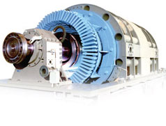
Generator Protection
GE Vernova's generator protection devices provide innovative solutions for the...
View MoreMultilin™ P30 - Legacy
Phasor Data Concentrator
Manufacturing for this product has been discontinued. Please contact us to discuss alternatives.
GE Vernova's series of Multilin P30 PDCs and PMU devices leverage the latest advances in synchrophasor and computing technologies available for the power industry to enable synchrophasor based wide area monitoring applications.
Multilin™ P30 - Legacy
Phasor Data Concentrator
Manufacturing for this product has been discontinued. Please contact us to discuss alternatives.
GE Vernova's series of Multilin P30 PDCs and PMU devices leverage the latest advances in synchrophasor and computing technologies available for the power industry to enable synchrophasor based wide area monitoring applications.
Overview
Monitoring of electrical grid infrastructure is a critical task carried out continuously by system operators to guarantee safe and reliable operations. Traditional SCADA systems give operators a view of the system's operating conditions with a typical latency in the range of seconds and minutes.
The relative low measurement frequency and low speed communications combined with the time required to execute analysis programs do not allow SCADA systems to handle system emergency operations in real time. Decisions are made based on static power system models where a trade-off with accuracy is generally needed.
Communication and computing technologies available today allow monitoring functions with sub cycle resolution for power systems over large geographical areas. The faster and higher resolution measurements introduced with synchrophasor technologies, also known as dynamic monitoring capabilities, enable wide area monitoring at the system level based on accurate and precise data at high-speed data rates with extremely low latency, less than 200ms.
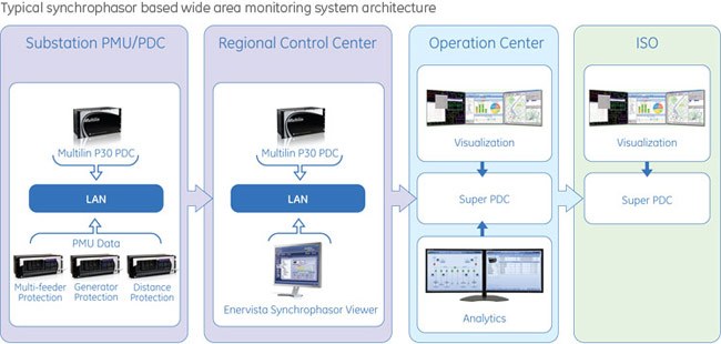
When applied to wide area applications, typically executed at the operation center level, synchrophasors enable operators to optimize system availability, reliability and stability analysis and operations. Phasor Data Concentrators (PDCs) and the Phasor Measurement Units (PMUs), that supply control centers with phasor data, are key components of synchrophasor based wide area monitoring systems.
Wide Area Monitoring
Enabling Synchrophasor Based Wide Area Monitoring
Reduce synchrophasor based wide area monitoring deployment and maintenance cost by integrating more PMUs per PDC, while being compliant to NERC-PRC-002-2 dynamic disturbance recording requirements:
- Integration of Phasor Measurement Units (PMUs)
- Seamless Interface to Super PDCs
- Integrate any C37.118 compliant device
Connectivity
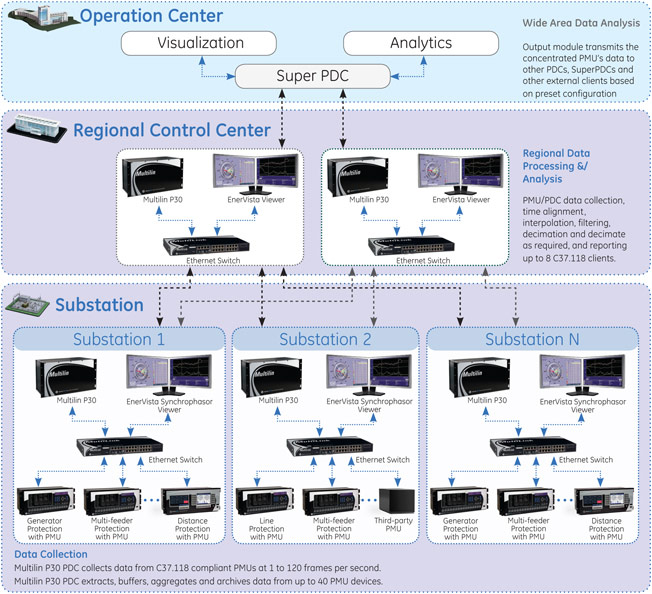
The Multilin P30 Phasor Data Concentrator is a modular, substation rated, high performance device capable of collecting, processing, recording and archiving C37.118 compliant synchrophasor data. The Multilin P30 supports up to forty PMU or PDC inputs and up to eight user configurable channels for transmission of synchrophasor data to clients such as other PDCs, Super PDCs and/or EnerVista Synchrophasor Viewer.
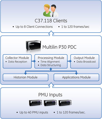 Multilin P30 Phasor Data Concentrator product architecture
High Performance PDC
![]() The primary function of the Multilin P30 PDC is to provide enhanced visibility of the electrical power grid. The Multilin P30 PDC data collector module communicates with up to forty PMUs or other PDCs to acquire and time-align synchrophasor data.
The primary function of the Multilin P30 PDC is to provide enhanced visibility of the electrical power grid. The Multilin P30 PDC data collector module communicates with up to forty PMUs or other PDCs to acquire and time-align synchrophasor data.
![]()
The Multilin P30 processor module structures output datasets from available data, interpolates, filters and decimates data as required.
![]()
The Multilin P30 PDC can connect to up to eight output streams which can be individually configured to ensure clients such as other PDCs, Super PDCs, visualization devices, external historians and other external applications receive accurate and precise data at rates previously impossible to obtain from traditional SCADA systems.
Easy Expansion and Customization of Multilin P30 PDC
![]() The Multilin P30 Applications Processor option is available to users that need to integrate custom applications into their synchrophasor monitoring systems.
The Multilin P30 Applications Processor option is available to users that need to integrate custom applications into their synchrophasor monitoring systems.
![]()
The Multilin P30 Applications Processor is equipped with a Windows® operating system that allows installation of user's preferred applications including development tool kits.
![]()
The Multilin P30 Applications Processor can reduce DDR systems deployment cost leveraging the infrastructure built in to the Multilin P30 PDC to expand and customize the PDC platform while maintaining the system reliability associated with the Multilin P30 substation rated platform.
Recording and Archiving
PRC-002-2 Dynamic Disturbance Recording (DDR)
PRC-002 is a standard under development that will define the requirements for recording and reporting Sequence Of Events (SOE) data, Fault Recording (FR) data, and Dynamic Disturbance Recording (DDR). The purpose of the standard is to facilitate analysis of disturbances.
FR and SOE are features commonly available today in protection relays and SCADA equipment.
The third type of recording defined in the PRC-002-2 standard is DDR. Large interconnected systems can have inter-area responses to each other resulting in slow oscillating load swings. These disturbances are characterized by oscillating power swings that can have frequencies in the neighborhood of 0.1 to 4Hz, and duration in the range of a few seconds to minutes or hours.
A dynamic disturbance recorder is a device cable of recording incidents that portray power system behavior during dynamic events such as low frequency (0.1Hz - 4Hz) oscillations and abnormal frequency or voltage excursions.
The advanced high capacity disturbance and event recording features available in the Multilin P30 Substation Phasor Data Concentrator support the requirements of the PRC-002-2 standard and can significantly reduce the time needed for analysis and reporting of disturbance analysis and regulatory reports.
![]()
Multilin P30 Built-in Historian Capabilities
A typical GE Vernova substation Dynamic Disturbance Recording (DDR) system comprises of several PMUs reporting synchrophasor data at various different rates from 1 to 120 frames per second to a Multilin P30 PDC. Each of GE Vernova's Multilin PMUs may include 1 to 14 sets of phasor values (Multilin N60). Below are some typical examples of different types of PMUs with various combinations of phasor, analog and digital parameters. Large volumes of data generated by a DDR system requires a fast and reliable archiving method to guarantee data integrity for future analysis.
The Multilin P30 PDC historian processor is a high capacity platform capable of recording up to 100.000 values per second.
![]()
Local Archiving
Distributed synchrophasor data storage through local archiving is recommended under the following two scenarios:
- 1. Upstream communication channels don't support the bandwidth to report all data monitored by the PDC.
- 2. Communication channels supports transmission of all data monitored by the Multilin P30 PDC. Archiving at the Substation level is
introduced to increase system reliability and preserve monitored data in case of upstream channel communications failure.
Multilin P30 PMU Input Type Examples
Software Options
EnerVista™ P30 Setup Software
The EnerVista P30 Setup software follows the user friendly structure characteristic of the industry leading EnerVista suite of software applications.
The EnerVista P30 Setup application provides easy access to the Multilin P30 PDC feature set through an intuitive tree view of the Multilin P30 parameters for a clear and simple configuration process. A series of convenient trouble-shooting and diagnostic tools such as trending, Multilin P30 sequence of events recorder live view of actual values is available in EnerVista P30 Setup to optimize the testing, commissioning and monitoring activities.
The Multilin P30 Setup software can operate without a Multilin P30 device physically connected to the computer allowing users to work on configuration projects and save settings in a configuration file for future use.

EnerVista Synchrophasor Viewer Software
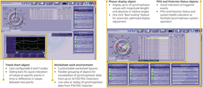
EnerVista Synchrophasor Viewer is a powerful yet simple to use synchrophasor data management and visualization tool. EnerVista Synchrophasor Viewer can be customized to provide different views of the power system in a time aligned, live view or time aligned replay of historical events over user defined time span.
The visualization interface is based on an easy to use "worksheet" work environment. Users can create multiple worksheets on which multiple user configurable objects such as Phasor Displays, Trend Charts, Historian Statistics and PMU Status tables are displayed.
EnerVista Synchrophasor Viewer supports up to 16 Multilin P30 historians simultaneously. Each historian can be accessed by up to seven concurrent users.
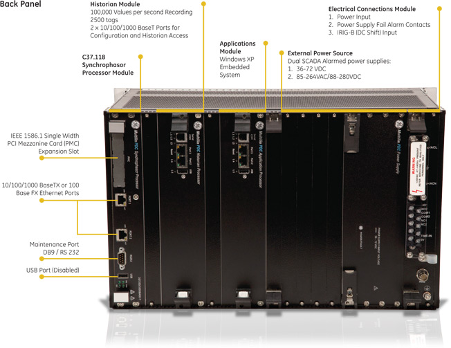
Hardware Overview
Recommended Products & services

P161, P162 & P163 - Legacy
Manufacturing for this product has been discontinued. As an alternative, please refer to the 850 relay.
P161, P162 & P163 - Legacy
Manufacturing for this product has been discontinued. As an alternative, please refer to the 850 relay.
Recommended Products & services

Feeder Protection
GE Vernova’s distribution feeder protection systems provide advanced protection with...
View MoreNBV Voltage Unbalance Relay - Legacy
Manufacturing for NBV has been discontinued. As an alternative, please refer BA300 for battery monitor application.
NBV Voltage Unbalance Relay - Legacy
Manufacturing for NBV has been discontinued. As an alternative, please refer BA300 for battery monitor application.
Recommended Products & services
NBT Breaker Trip Circuit Supervision - Legacy
Manufacturing for this product has been discontinued. For more information, contact us.
The type NBT relays have been designed to supervise the voltage level and electrical continuity in the tripping circuit of a circuit breaker.
Protection and Control
- Undervoltage and overvoltage
- Defective phase identification

NAA Auxiliary Relay - Legacy
The NAA will be discontinued as of October 1, 2013.
Read full notice
NAA Auxiliary Relay - Legacy
The NAA will be discontinued as of October 1, 2013.
Read full notice
MVTT
Time Delay Relays
The MVTT range is comprised of static time delay relays for use in all types of protection, control or automation schemes. The MVTT static time delay relays have the flexibility to be used in any type of protection, control or automation schemes. They have a wide setting range and are compact in design.
MVAJ 11 to 34 Trip Relays - Legacy
The MVAJ 11 to 34 range complements the more cost-effective range of MVAJ051 to MVAJ205 tripping relays. This range has been maintained to cater to historical users and their preference for these models. This range of tripping relays benefits from its high-speed operation and offers high and low burden alternatives. These particular models are kept to cater to historical users.
MultiNet4 - Legacy
Multi-Port Serial Server & Management Switch
Sales of this product have been discontinued. As an alternative, please refer to MDS Orbit MCR.
MultiNet4 - Legacy
Multi-Port Serial Server & Management Switch
Sales of this product have been discontinued. As an alternative, please refer to MDS Orbit MCR.