HFC Instantaneous Overcurrent Relay - Legacy
Manufacturing for this product has been discontinued. As an alternative, please refer to the 3 Series relays and MII Family.
HFC Instantaneous Overcurrent Relay - Legacy
Manufacturing for this product has been discontinued. As an alternative, please refer to the 3 Series relays and MII Family.
Recommended Products & services
Multilin HardFiber System - Legacy
IEC 61850 Process Bus Solutions
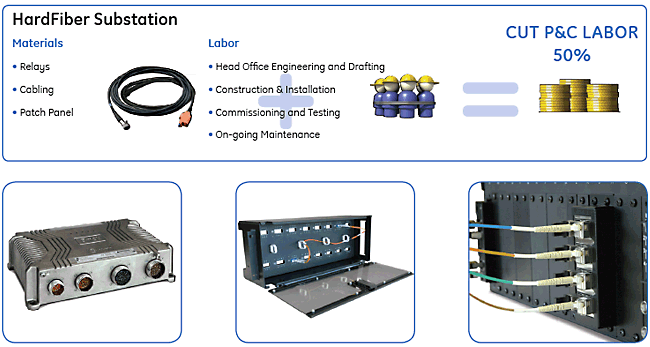
The Multilin HardFiber System is an IEC 61850 Process Bus Solution that allows the mapping of measurements made in the switchyard to protection relays located in the control house using secure communications. The HardFiber System is designed to reduce the overall labor associated with the tasks of designing, documenting, installing and testing protection and control systems. By specifically targeting copper wiring and all of the labor it requires, the HardFiber System allows for greater utilization and optimization of resources.
Multilin HardFiber System - Legacy
IEC 61850 Process Bus Solutions
The Multilin HardFiber System is an IEC 61850 Process Bus Solution that allows the mapping of measurements made in the switchyard to protection relays located in the control house using secure communications. The HardFiber System is designed to reduce the overall labor associated with the tasks of designing, documenting, installing and testing protection and control systems. By specifically targeting copper wiring and all of the labor it requires, the HardFiber System allows for greater utilization and optimization of resources.
An Industrial Revolution for Protection & Control
The HardFiber Process Bus System represents a true breakthrough in the installation and ownership of protection and control systems, by reducing the overall labor required for substation design, construction, and testing. This innovative solution addresses the three key issues driving the labor required for protection and control design, construction and testing:
- Every substation is unique making design and drafting a one-off solution for every station
- Miles of copper wires needs to be pulled, spliced and terminated
- Time consuming testing and troubleshooting of thousands of connections must be performed by skilled personnel
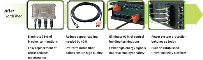
The HardFiber System was designed to address these challenges and reduce the overall labor associated with the tasks of designing, documenting, installing and testing protection and control systems. By specifically targeting copper wiring and all of the labor it requires, the HardFiber System allows for greater utilization and optimization of resources with the ultimate goal of reducing the Total Life Cost (TLC) for protection & control.
Key Benefits of the HardFiber System
The underlying driver for the HardFiber System is the reduction of Total Life Costs of protection and control through labor and resource optimization. This optimization is achieved by replacing individual, labor-intensive, individually terminated copper wires with standardized physical interfaces and open digital communications.
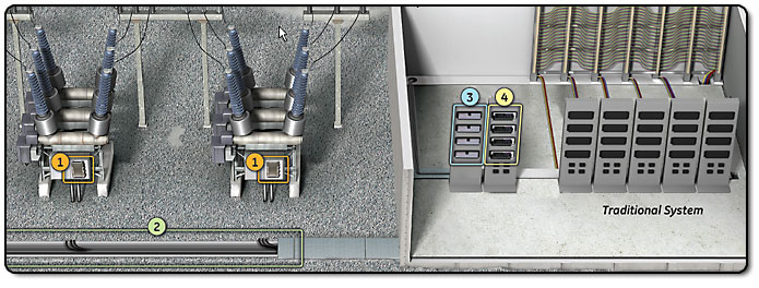
Traditional substation designs require large amounts of skilled labor to create engineering drawings, pull and terminate miles of copper cables, and test and troubleshoot thousands of connections.
Multilin HardFiber Options
- S-Brick. S-Brick with Standard Kiosk Case.
- Manufacturing for the Brick with the Ruggedized Switchyard Hardened Interface has been discontinued. As an alternative, please refer to MU320E.
 The HardFiber System replaces labor-intensive processes with quick installation, off-the-shelf equipment and made-to-order cables.
Ruggedized Brick
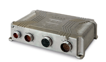
The HardFiber Brick Process Interface Unit (Order Code BRICK-4-HI-R-****-R-X-X) is ruggedized I/O device designed for mounting outdoors in utility switchyards with 8 analog measurements, either 4 currents / 4 voltages, or 8 currents, along with 18 contact inputs, 3 universal DC inputs, 4 Form-A tripping contacts, 2 Form-C signaling contacts, and latching contact. The Brick uses connectorized copper and fiber optic cables for ease of installation and for environmental protection. The R-Brick works directly with models of the GE Vernova Universal Relay (UR) family. Manufacturing for the Brick with the Ruggedized Switchyard Hardened Interface has been discontinued. As an alternative, please refer to MU320E.
Fiber cable options for the Brick
Manufacturing for the Brick Cables have been discontinued.
Custom FOA cable
The custom FOA cables are ordered to length and are connectorized at each end. These FOA cables require the use of the Cross Connect Panel, and the FOR Indoor Relay Fiber Cable, to connect to the UR relay. DC power to the Brick is distributed by the Cross Connect Panel, and short circuit protection for the Brick power supply is included in the FOA cable.
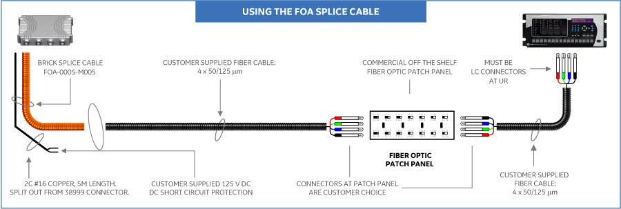
FOA Splice cable
The FOA Splice Cable is intended to meet customer standards for fiber optic cable distribution through the switchyard. The FOA Splice Cable is connectorized at the Brick end and ends in copper and fiber pigtails. The customer must provide their own fiber optic cables across the switchyard, DC supply to power the Brick, DC short circuit protection for the Brick power supply, and perform their own splicing to the pigtails of the FOA Splice Cable
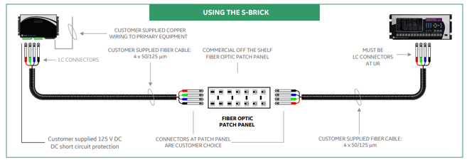
S-Brick Process Interface Unit
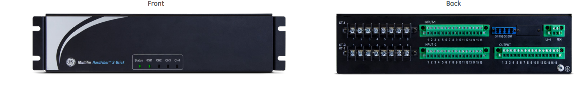
The HardFiber S-Brick Process Interface Unit (Order Code: BRICK-4-HI-S- ****-*-X-X) is intended for mounting inside marshalling cabinets, kiosks, and equipment control cabinets. The S-Bricks have 8 analog measurements, either 4 currents / 4 voltages, or 8 currents, along with 18 contact inputs, 3 universal DC inputs, 4 Form-A tripping contacts, 2 Form-C signaling contacts, and latching contact. It uses standard terminal blocks for connecting copper cables to interface with primary equipment. Fiber optic cables require the use of one simplex LC connector for each of the four fiber optic cores. The HardFiber S-Brick Process Interface Unit works directly with models of the GE Vernova Universal Relay (UR) family. The S-Brick requires the customer to provide copper cabling to interface with primary equipment, DC supply to power the S-Brick, and fiber optic cabling and cabling management between the S-Brick and end device
Fiber optic cabling
The Multilin HardFiber System requires the use of 50/125 mm multimode fiber, that support 1310nm and 1550nm transmission. Class 1 graded index fiber is ideal. In general, OM2 and OM3 rated fibers meet these requirements. Environmental rating of the fiber cables is as per customer application. The S-Brick and the UR have female LC connectors, so cables must use male LC connectors at these ends. The S-Brick has 4 LC connectors, while the UR has 8 LC connectors. Commercially available fiber optic patch panels may be used for cable management. The customer must provide a 125 or 250 VDC rated supply to power the S-Brick. The DC circuit must provide short circuit protection for the S-Brick power supply, (1A, fast acting, 10,000 A DC interrupting capacity, Littelfuse KLKD001 or equivalent). The general recommendation is to power the S-Brick separately from the associated primary equipment for good operating and maintenance practices.
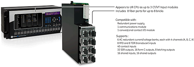
Universal Relay IEC 61850 Process Card
- Communications interface between the relay and up to eight Bricks, including synchronization, data alignment and contact input processing
- Transmits commands to connected Bricks to operate primary power system apparatus
- Real-time system health monitoring and data cross-checking — unprecedented level of error detection and security
Save up to 50% on your P&C Labor Costs

System Architecture
The architecture of the HardFiber System is driven by the mapping of signals between the primary apparatus and the protection and control devices. The measurement of field signals and respective mapping of these signals, using the open IEC 61850 communications protocol, back to the control house is done through a hardened interface device called the HardFiber Brick.
Using made-to-order Outdoor Fiber Cables connecting the Brick to a Cross Connect Panel in the control house provides fast and error-proof installation without the need for on-site splicing or terminating.
Keeping true to the existing topology of traditional substations, each protection and control device included in the zone of protection will be connected directly to Bricks through dedicated fiber optic connections.
This simple, purpose-driven architecture that uses the IEC 61850 open standard for communications, provides dedicated point-to-point connections between the Brick and protective relays without introducing any issues relating to data synchronization, setting management or Cyber Security.
 Each Brick transmits measurements and accepts controls from up to 4 separate protection and control devices.
Scalability
The true test of any system, including a Process Bus system, is its ability to incrementally scale up to meet specific applications without adversely affecting the other devices in the system. Today’s protection and control systems are already naturally scalable.
The challenge for communication-based protection systems becomes making extensions and modifications without disrupting the in-service protection and control system.
By recognizing that the mapping between power system signals and protection and control devices is fundamentally driven by the topology of the underlying substation, the HardFiber System is optimally partitioned and connected to allow for additions, modifications and upgrades to the system – without risking interruption or degradation to critical in-service protection.
Reliability, Dependability, Security
The HardFiber System provides an unprecedented level of diagnostics and self-checking, allowing critical protection and control systems to do something that they have never done before – operate without routine maintenance.
Internal diagnostics and self-tests within each Brick monitor dozens of critical internal subsystems and provide this information several hundred times per second. Duplicate Bricks can be provisioned to acquire each input signal twice, allowing protection and control devices to continuously crosscheck critical protection measurements before executing commands via fully redundant outputs.
With the HardFiber redundant architecture, each protection and control device can be configured to maximize dependability and security, addressing specific application requirements.
Recommended Products & services
Merging Units
Merging units are a key element of the process bus concept, enabling the digitization of...
View MoreGXS Automatic Synchronizing Relay - Legacy
Manufacturing for GXS has been discontinued. As an alternative, please refer to 850 or P94V.
GXS Automatic Synchronizing Relay - Legacy
Manufacturing for GXS has been discontinued. As an alternative, please refer to 850 or P94V.
Recommended Products & services
GSY Mho Distance Relay - Legacy
Manufacturing for this product has been discontinued. As an alternative, please refer to the 3 Series relays.
GSY Mho Distance Relay - Legacy
Manufacturing for this product has been discontinued. As an alternative, please refer to the 3 Series relays.
Recommended Products & services
Genesis Software - Legacy
Supply of Genesis Software for the DDS Family of products has been discontinued.
Genesis Software is comprised of multiple tools for viewing & configuring settings, and viewing oscillography data in graphical form. It is used in the following DDS Family products:
Genesis Software - Legacy
Supply of Genesis Software for the DDS Family of products has been discontinued.
Genesis Software is comprised of multiple tools for viewing & configuring settings, and viewing oscillography data in graphical form. It is used in the following DDS Family products:
Recommended Products & services

Feeder Protection
GE Vernova’s distribution feeder protection systems provide advanced protection with...
View MoreGE Vernova Communicator
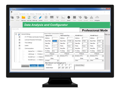
Advanced Setup, Logging, Visualization, and Analysis Software for EPM Meters
GE Vernova Communicator is an easy-to-use software application to setup and maintain EPM meters as well as view data and generate reports to support analysis. It provides advanced visualization functionality including graphing/trending values; viewing waveforms/log records; and generating customizable reports. Furthermore, with MeterManager, meters can be grouped together, meter diagnostics and status can be determined, and data can be automatically retrieved at intervals for report generation.
GE Vernova Communicator
Advanced Setup, Logging, Visualization, and Analysis Software for EPM Meters
GE Vernova Communicator is an easy-to-use software application to setup and maintain EPM meters as well as view data and generate reports to support analysis. It provides advanced visualization functionality including graphing/trending values; viewing waveforms/log records; and generating customizable reports. Furthermore, with MeterManager, meters can be grouped together, meter diagnostics and status can be determined, and data can be automatically retrieved at intervals for report generation.
Key Benefits
- User-friendly software interface for easy setup and commissioning of EPM meters
- Simplified and accurate data collection and presentation of key, real-time collected meter information such as voltage, current, power and energy, time of use, power quality, harmonics, waveforms, alarm/limits, and I/O status
- Support for integration with other software packages with ODBC-compliant database structures
- Two versions – GE Vernova Communicator for setup and basic data visualization and GE Vernova Communicator (Licensed) for meter system setup, automated data retrieval, and advanced visualization and analysis
Applications
- View and compare multiple values, circuits, and waveforms from one or more events
- Easily zoom/pan, mark, and add annotations to waveform records for detailed analysis
- Baseline and monitor data for impact and performance reviews
| FEATURE | GE VERNOVA COMMUNICATOR | GE VERNOVA COMMUNICATOR PROFESSIONAL (LICENSED) |
|---|---|---|
| Setup and configure GE Vernova EPM meters | • | • |
| Database storage of collected information for SQL searches and data mining | • | • |
| View basic charts and graphs; basic power quality waveform viewer | • | • |
| Auto-collect data using MeterManager automation server tools |
| • |
| Detect installation and quality of service issues |
| • |
| Create and email spreadsheet reports automatically on a set schedule |
| • |
| Generate PQDIF, COMTRADE, and HHF files |
| • |
| Integration to GE Vernova Energy Aggregator – Energy dashboard/reporting |
| • |
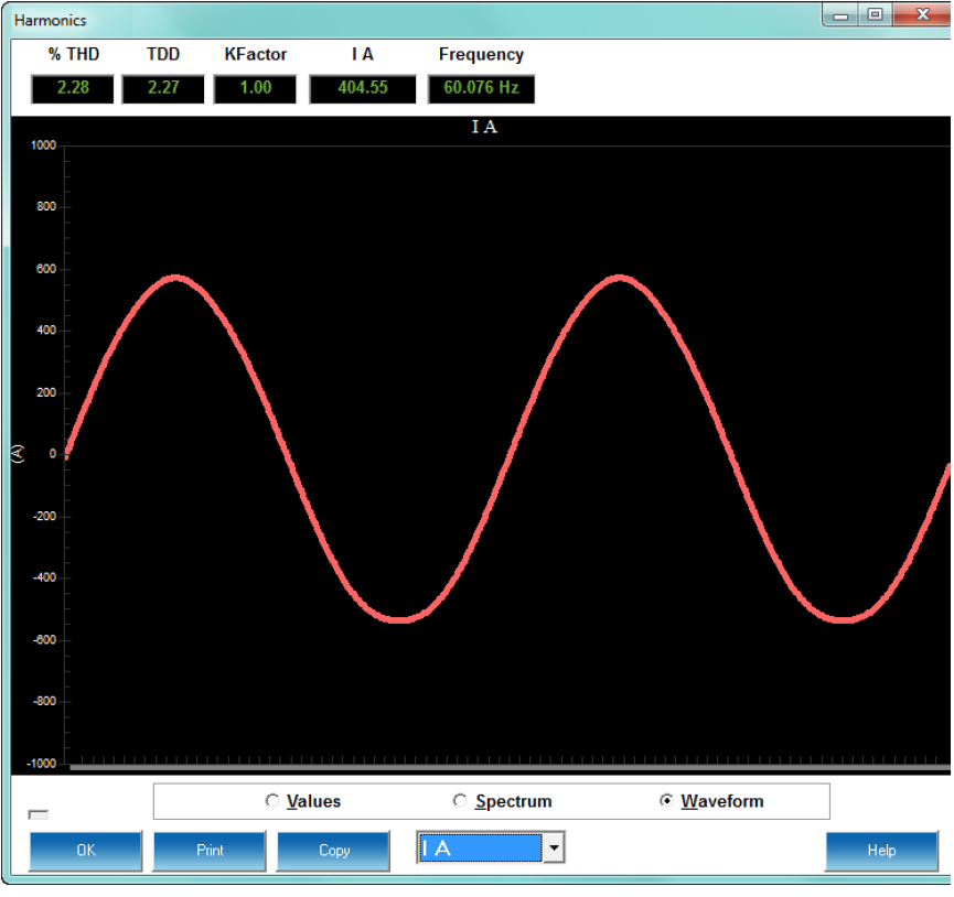 View Waveform Data
View Real-Time Data
GE Vernova Communicator connects to EPM Meters to view real-time data remotely and safely. Examples of data that can be viewed include voltage, current, power, and energy; time of use and accumulations; power quality; harmonic magnitudes; real-time waveform scopes; alarms and limits; max. and min. for each parameter; and I/O device information.
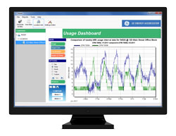
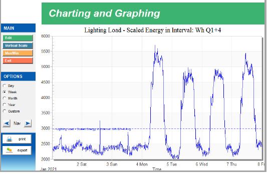 Visualize/Trend Energy Data
View Logged Data
The Log Viewer provides charting and graphing using database-driven, normalized data from GE Vernova EPM Meters. The charts and graphs provide concise visualization to help interpret retrieved data support analysis.
Features include:
- Tabular data format to support spreadsheets
- Multi-pen charting and graphing
- View data by month, day, or year
- Plotted max. and min. values
- Zoom and pan of graphs
- Cut/paste functionality
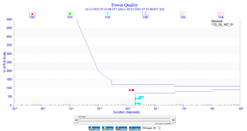 View CBEMA and Other Power Quality Indices
Advanced Power Quality Visualization, Charting, and Graphing
GE Vernova Communicator supports advanced visualization of power quality information in various industry standard formats including a scatter graph, providing CBEMA plotting information. The CBEMA plot gives definition to the severity of events and their effect on equipment. For example, if multiple events fall outside the CBEMA tolerances, the monitored equipment may be damaged. Furthermore, visualizations such as 3D plots and histograms with frequency and severity of power quality events can also be shown.
- View ITIC, Semi F47, CBEMA, and other industry-standard graphs
- View time waveform events using millisecond resolution
- Sort data by fault type
- Compare information from circuits
- Review impact of changes to protective equipment
- Monitor and analyze performance metrics
- Conduct post/forensic analysis of events
- View cycle-by-cycle RMS trends
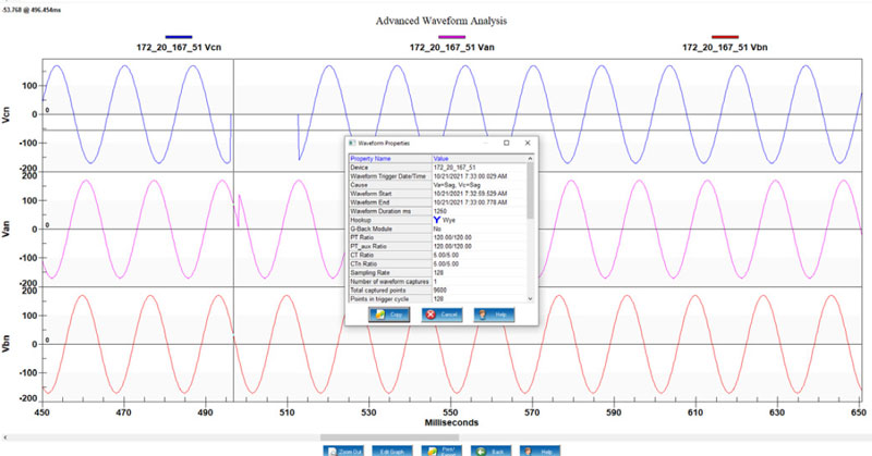 Analyze Waveform Records
View Waveform Records
GE Vernova Communicator provides easy-to-use visualization of waveform data for fast and simple analysis. Various views illustrate stored information graphically such as phasors for easy troubleshooting, as well as waveforms of events caused by power quality problems, faults, transients, and other conditions.
Features include:
- View, zoom/pan, and compare multiple waveforms from one or more events
- Conduct harmonic analysis of waveform data using harmonic magnitudes, peak value, and RMS readings per cycle
- Add databased annotations to waveform records
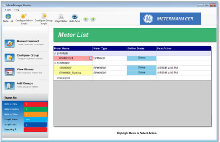 Group and see status of meters
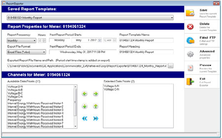 Configure automatic reports
Meter Management System
GE Vernova’s MeterManager is available with the GE Vernova Communicator Professional (Licensed) version and provides a comprehensive meter management system, with report generation, and data collection for up to 1,200 Ethernet-connected meters.
Automated Status, Report Generation, and Export
GE Vernova MeterManager’s Report Exporter provides design of customized reports of meter data. Reports can be generated for one or more meters and can be set up for automatic report generation at specific intervals (e.g., hourly, multi-hourly, daily, weekly, or monthly). Report Exporter can also export reports via email and upload reports via FTP to a central location for viewing.
System Requirements
| System Requirements | |
|---|---|
| Supported Operating Systems |
|
| Memory |
|
| Storage |
|
| Other |
|
GDC Current Detecting Relay - Legacy
The GDC is a current detecting relay with detection being made by means of voltage applied to a high impedance unit. These relays are provided with measuring elements and are used mainly for the detection of restricted ground faults in transformers and rotating synchronous and asynchronous machines.
Applications
- Transformer circulating current protection circuits
Recommended Products & services
GCY Phase Packaged Directional-distance relay - Legacy
Manufacturing for GCY has been discontinued. As an alternative,please refer to 3 Series or MIIFamily.
GCY Phase Packaged Directional-distance relay - Legacy
Manufacturing for GCY has been discontinued. As an alternative,please refer to 3 Series or MIIFamily.
Recommended Products & services
GCX Phase Packaged Directional-distance Relay - Legacy
Manufacturing for this product has been discontinued. As an alternative, please refer to the 3 Series relays.
GCX Phase Packaged Directional-distance Relay - Legacy
Manufacturing for this product has been discontinued. As an alternative, please refer to the 3 Series relays.
Recommended Products & services
Gateways and RTUs
GE Vernova offers an industry-leading suite of multifunction servers, gateways, RTUs, and data concentrators for automating substation equipment and providing visibility to critical electrical assets found across the transmission and distribution power grids.
Gateways and RTUs
GE Vernova offers an industry-leading suite of multifunction servers, gateways, RTUs, and data concentrators for automating substation equipment and providing visibility to critical electrical assets found across the transmission and distribution power grids.

Multilin G100
The G100 substation gateway offers a high-capacity, secure, modular, and substation-hardened set of hardware and software components designed to simplify the deployment, operation, and maintenance of automation systems – all in a compact form-factor for space constrained panels or cubicles.
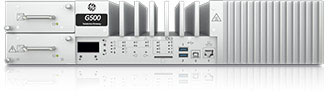
Multilin G500
The G500 substation gateway provides reliable and accurate collection of data from serial or LAN-based intelligent substation devices. It offers data logging, protocol conversion and runs automation applications, while consolidating functions such as HMI, Ethernet communications, time synchronization and cyber security features.

Not finding the Gateway or RTU that you’re looking for? View legacy gateway & RTU products.
Recommended Products & services

Gateways and RTUs
GE Vernova offers an industry-leading suite of multifunction servers, gateways, RTUs, and...
View More