Optimized motor protection to ensure maximum process uptime.
Category image
Interactive link
Has legacy products
On
Overview
Overview Back Link
Optimized motor protection to ensure maximum process uptime.
Manufacturing for the MM200 has been discontinued. As an alternative, please refer to MM300 Enhanced.
Manufacturing for the MM200 has been discontinued. As an alternative, please refer to MM300 Enhanced.
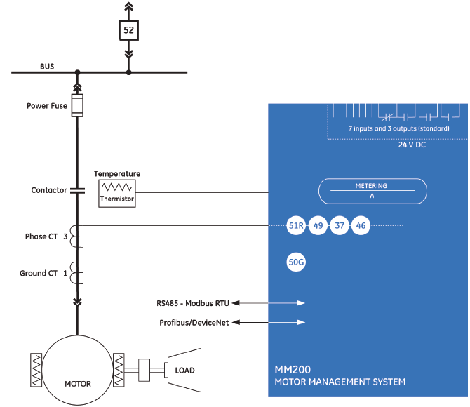
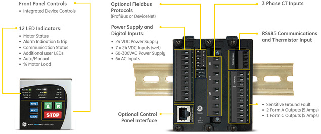
The MM200 includes high accuracy metering of current signals. Current parameters are available as total RMS magnitude.
The MM200 provides ten digital counters to aid in system analysis. The digital counters can be used for scheduling inspections on equipment, performing qualitative analysis of system problems and spotting trends.
Monitoring the motor’s operating characteristics assists in determining the motor start parameters and is a critical tool for determining the operating characteristics of the system, motor and connected load.
The MM200 performs comprehensive device health diagnostic tests during startup and continuously at runtime to test its own major functions and critical hardware. These diagnostic tests monitor for conditions that could impact the MM200’s performance, evaluate the criticality of this impact and present device status via SCADA communications. Providing continuous monitoring and early detection of possible issues helps improve system availability by employing predictive maintenance
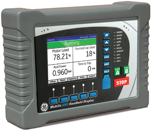
The Hand Held Display (HHD) provides a rugged local interface for MM200 Motor Protection Systems where a local display is not used in the MCC.
The HHD provides a graphical color local interface to the MM200 Motor Protection Systems allowing local operators to view and change setting files and quickly access relay diagnostic information.
The HHD provides a clear and detailed view of all motor settings, diagnostic information and metering data available in the MM200 allowing local operators to make informed decisions on the motors operation.
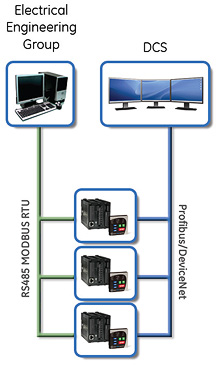
The MM200 utilizes the most advanced communications technologies available today making it an easier and more flexible motor protection relay to use and integrate into new and existing infrastructures. Multiple communication ports and protocols allow control and easy access to information from the MM200. All communication ports are capable of communication simultaneously.
The MM200 supports the most popular industry standard protocols enabling easy, direct integration into HMI and electrical SCADA systems. Modbus RTU is provided standard with a RS485 networking port. The following optional protocols and communication ports are available:
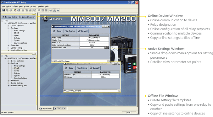
The EnerVista™ Suite is an industry-leading set of software programs that simplifies every aspect of using the MM200 relay. The EnerVista™ suite provides all the tools to monitor the status of the protected asset, maintain the relay, and integrate information measured by the MM200 into DCS or SCADA monitoring systems.
Learn more![]()

GE Vernova’s motor protection systems use advanced thermal modeling to provide...
View MoreManufacturing for this product has been discontinued. As an alternative, please refer to the MM300 relays.
Manufacturing for this product has been discontinued. As an alternative, please refer to the MM300 relays.
GE Vernova’s motor protection systems use advanced thermal modeling to provide...
View MoreManufacturing for 469 has been discontinued. As an alternative, please refer to the 859 or 869 relays.
Manufacturing for 469 has been discontinued. As an alternative, please refer to the 859 or 869 relays.
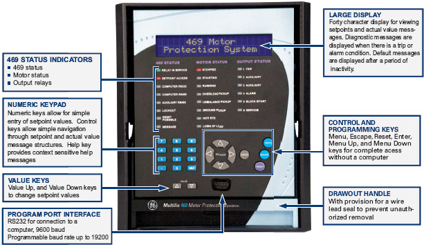
The 469 is a digital motor protection system designed to protect and manage medium and large motors and driven equipment. It contains a full range of selectively enabled, self contained protection and control elements as detailed in the Functional Block Diagram and Features table.
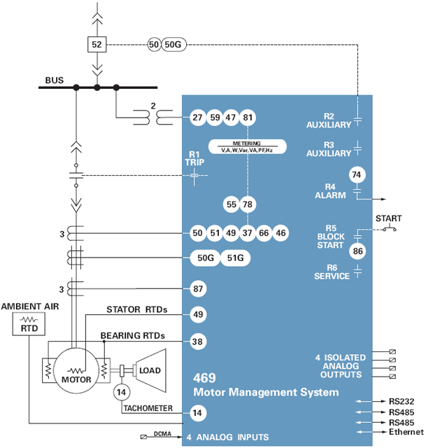
The 469 includes high accuracy metering and recording for all AC signals. Voltage,current, RTD and power metering are built into the relay as a standard feature.
The following system values are accurately metered and displayed: Phase, differential and ground currents, average current, motor load, current unbalance. Phase-to-ground and Phase-to-phase voltages, average phase voltage, system frequency. Real, reactive, apparent power, power factor, watthours, varhours, torque Current and power demand. Analog inputs and RTD temperatures. Thermal capacity used, lockout times, motor speed
The 469 is equipped with monitoring tools to capture data. The following information is presented in a suitable format.
The event recorder stores motor and system information with a date and time stamp each time a system event occurs. Up to 256 events are recorded.
The 469 records up to 128 cycles with 12 samples per cycle of waveform data for 10 waveforms (Ia, Ib, Ic, Ig, Diffa, Diffb, Diffc, Va, Vb, Vc) each time a trip occurs. The record is date and time stamped.
The Multilin 469 provides advanced motor diagnostics including a broken rotor bar detection function. The broken rotor bar detection is a condition maintenance function that continuously monitors the motor’s health while in operation. The advanced Motor Current Signature Analysis (MCSA) continuously analyzes the motor current signature and based on preset algorithms will determine when a broken rotor bar is present in the motor.
 View motor status using digital inputs, analog inputs and RTD inputs
Multiple Protocols - Modbus RTU, Modbus TCP/IP, DeviceNet
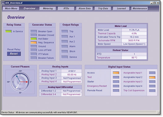
The EnerVista™ Suite is an industry leading set of software programs that will simplify every aspect of using the 469 relay. Tools to monitor the status of your motor, maintain your relay, and integrate information measured by the 469 into HMI or SCADA monitoring systems are available. Also provided are the utilities to analyze the cause of faults and system disturbances using the powerful Waveform and Sequence of Event viewers that come with the 469 Setup Software that is included with each relay. Learn More
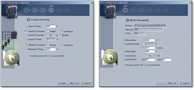 Create complete settings files for your SR469 in 6 simple steps using the Motor Settings Auto-Configurator.
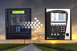 Explore the 8 Series Retrofit Kit
Traditionally, retrofitting an existing relay has been a challenging, time consuming task often requiring re-engineering, new drawings, panel modifications, re-wiring and re-testing.
The 8 Series Retrofit Kit provides a quick, 3-step solution to upgrade previously installed SR 469 relays. With the new 8 Series Retrofit Kit users are able to install the 869 Motor Protection System without modifying existing cutouts and wiring, and without any drawing changes or re-engineering time.
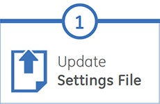
EnerVista 8 Series Setup Software provides automated setting file conversion. Once completed, a graphical report is provided to verify and call out any settings that need attention.
Simply remove the terminal blocks and then remove the SR chassis from the panel. No need to disconnect any of the field wiring.
Insert the new 8 Series Retrofit chassis into the switchgear and simply plug-in the old terminal blocks - there is no need to make any cut-out modifications or push and pull cables.
GE Vernova’s motor protection systems use advanced thermal modeling to provide...
View More