Optimized motor protection to ensure maximum process uptime.
Category image
Interactive link
Has legacy products
On
Overview
Overview Back Link
Optimized motor protection to ensure maximum process uptime.
Manufacturing for the 369 has been discontinued. As an alternative, please refer to 859.
Manufacturing for the 369 has been discontinued. As an alternative, please refer to 859.
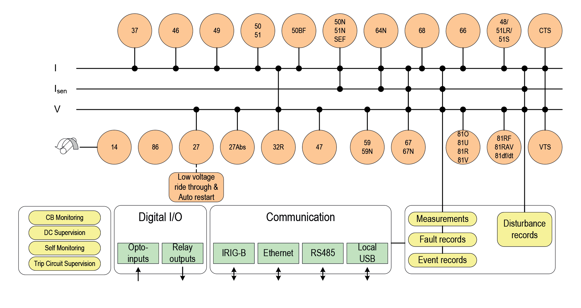
The 369 is a digital motor protection system designed to protect and manage medium sized AC motors and their driven equipment. It contains a full range of selectively enabled, self contained protection and control elements as detailed in the Functional Block Diagram and Features table.
The 369 offers a choice of optional monitoring and metering functions including:
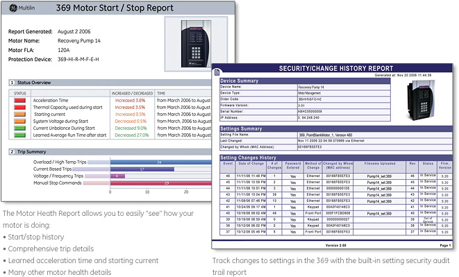
 Track changes in motor starting characteristics, identifying potential failures before they become critical
 Troubleshoot faults that occur during motor starts using the Motor Start Data logger.
A front RS232 port is provided for downloading setpoints and interrogating the relay using the EnerVista™ 369.
Three independent rear RS485 ports offer the customer flexibility and performance for their communication network. The 369 can
communicate at baud rates up to 19,200 bps using the industry standard Modbus® RTU protocol. Fiber optic (option F) Profibus interface (option P), DeviceNet (option D), and Ethernet (option E) ports are also available. The optional direct connect RJ45 Ethernet port can be used to connect the 369 to 10 Mbps Ethernet networks. The communication system of the 369 is designed to allow simultaneous communication via all ports.
Using Ethernet as the physical media to integrate the 369 to Local or Wide Area Networks replaces a multipoint wired
network (e.g., serial Modbus®), and eliminates expensive leased or dial-up connections, reducing operating costs.
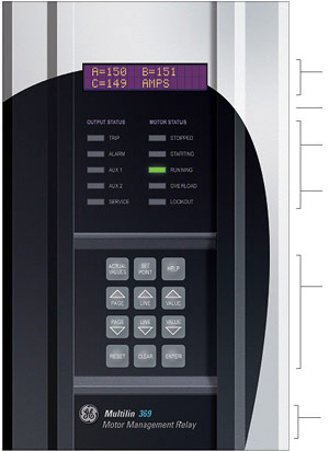
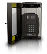
Display
40 Character LCD display for viewing actual values and programming setpoints Rugged, corrosion and flame retardant case
Status Indicators
4 LEDs indicate when an output is activated
Motor Status Indicators
LEDs indicated if motor Stopped, Starting, Running, Overloaded or Locked out due to an active Satart Inhibit element
Keypad
Used to display actual values, causes of alarms, causes of trips, fault diagnosis information, and to program setpoints
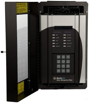
Computer Interface
RS232 comm part for connecting to a PC, Use for downloading setpoints, monitoring, data collection & printing reports
The EnerVista™ Suite is an industry leading set of software programs that will simplify every aspect of using the 369 relay. Tools to monitor the status of the motor, maintain the relay, and integrate information measured by the 369 into HMI or SCADA monitoring systems are available. Also provided are the utilities to analyze the cause of faults and system disturbances using the powerful waveform and Sequence of Event viewers that come with the EnerVista™ 369 Setup Software that is included with each relay. Learn More ![]()
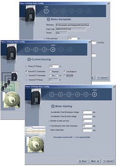
Automatically generate a complete settings file, eliminating the need to manually program hundreds of individual protection settings.

GE Vernova’s motor protection systems use advanced thermal modeling to provide...
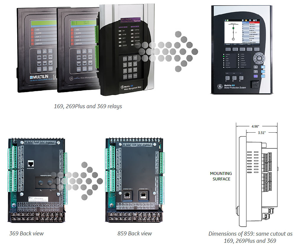
View MoreThe Multilin 859 is the only relay that offers a seamless, direct replacement for existing Multilin protection relays. Designed to fit the same mechanical cut and accept the same wiring connectors (applicable to 369 relays), the 859 provides a simplified replacement strategy – eliminating the need for drawing changes, re-wiring, and door modifications. While also significantly reducing any staff training requirements. Additional one-to-one wiring maps are available for other legacy Multilin motor protection relays, and automated setting file conversion and analysis tools ensure reduced configuration time and effort.
Easy 3-Step Process to Upgrade from 369 to 859, in as fast as 30 minutes
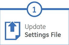
EnerVista 8 Series Setup Software provides automated setting file conversion. Once completed, the relay provides a graphical report to verify and call out any specific settings that might need attention
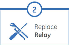
Simply unplug left and right terminal connectors and unscrew the upper and lower terminal wires to remove the 369 relay from the panel. No need to disconnect any of the field wiring*
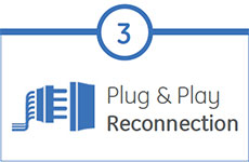
Mount the new 859 relay into the switchgear, plug in the old terminal blocks and reconnect the upper and lower terminal wires – there is no need to make any cut-outs modifications or push and pull old cables
* The panel and all wiring must be deenergized and safety procedures followed
Upgrade your 269 or 269Plus
Drawout to the 369 Drawout
GE Vernova’s motor protection systems use advanced thermal modeling to provide...
View MoreManufacturing for 239 has been discontinued. .
Manufacturing for 239 has been discontinued. .
GE Vernova’s motor protection systems use advanced thermal modeling to provide...
View MoreManufacturing for SPM has been discontinued. As an alternative, please consider the 869 with integrated SPM.
Manufacturing for SPM has been discontinued. As an alternative, please consider the 869 with integrated SPM.
GE Vernova’s motor protection systems use advanced thermal modeling to provide...
View MoreManufacturing for this product as been discontinued. As an alternative, please refer to the Multilin 369.
The MPM provides additional metering capabilities such as three phase voltage, pf, real power, reactive power, Wh, and frequency for the 269 or 269 Plus Motor Management Relay.
Manufacturing for this product as been discontinued. As an alternative, please refer to the Multilin 369.
The MPM provides additional metering capabilities such as three phase voltage, pf, real power, reactive power, Wh, and frequency for the 269 or 269 Plus Motor Management Relay.
GE Vernova’s motor protection systems use advanced thermal modeling to provide...
View MoreType MMC 1000 digital relays are microprocessor-based motor protectors that provide thermal protection for three phase AC motors, protection against phase to phase faults, phase to ground faults, single phase starts, excessively long starts, locked rotor and provide the additional optional functions of undercurrent and successive starts.
Type MMC 1000 digital relays are microprocessor-based motor protectors that provide thermal protection for three phase AC motors, protection against phase to phase faults, phase to ground faults, single phase starts, excessively long starts, locked rotor and provide the additional optional functions of undercurrent and successive starts.
GE Vernova’s motor protection systems use advanced thermal modeling to provide...
View MoreManufacturing for this product has been discontinued. As an alternative, please refer to the MM200 and MM300 relays.
Manufacturing for this product has been discontinued. As an alternative, please refer to the MM200 and MM300 relays.
GE Vernova’s motor protection systems use advanced thermal modeling to provide...
View MoreManufacturing for MM2 has been discontinued. As an alternative, please refer to MM300E.
Manufacturing for MM2 has been discontinued. As an alternative, please refer to MM300E.
GE Vernova’s motor protection systems use advanced thermal modeling to provide...
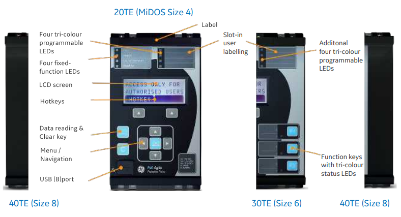
View MoreThe P24xM Series (P24NM, P24DM) deliver field proven protection, measurement and control algorithms built from GE Vernova’s P40 Agile range of protective devices.
The P24NM and P24DM devices offer multi-stage independent protection elements including a variety of curves in four setting groups. Machine thermal imaging monitoring, start supervision, and circuit breaker condition monitoring ensure maximum process uptime and system reliability.
The P24xM Series offers flexible and redundant communications options, simplifying device integration into SCADA or DCS systems.
Two communication ports are standard - a rear port providing remote communications and a front port for local operators. The front USB port allows the programming of settings, configuration of the programmable scheme logic, extraction and viewing of event, disturbance and fault records, viewing of measurements and the instigation of control functions.
The P24xM series supports the following advanced communication protocols:
IEC 61850 or DNP 3.0 over Ethernet are available when the optional Ethernet port is ordered in the 30TE and 40TE models. Redundant Ethernet protocol PRP, HSR and RSTP are also available in dual RJ45 or dual fiber. The copper physical link option uses RJ45 connectors, the fiber option uses LC connectors. IEC 61850 offers high-speed data exchange, peer-to-peer communication, reporting, disturbance record extraction and time synchronization. To help smooth transition from the existing protocol to the IEC 61850 protocol, the P40 Agile relay had been designed to provide concurrent Courier, Modbus or DNP3 on the RS485 while provide IEC 61850 over Ethernet port.
S1 Agile is the truly universal IED engineering toolsuite. No-longer are separate tools required for redundant Ethernet configuration, scheme operational dashboards, programmable curve profiles or automatic disturbance record extraction – all applications are embedded.
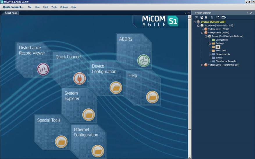
The front-panel interface allows direct IED interaction. . Integrated user function keys and tri-color programmable LEDs provide a cost-effective solution for control and annunciation.
GE Vernova’s motor protection systems use advanced thermal modeling to provide...
View More