RevenueSense
Current Transformers (600V)
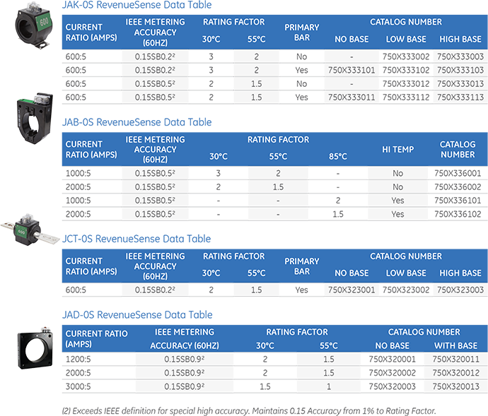
RevenueSense™ Current Transformers offer electrical utilities both extended range and high accuracy to reduce electrical losses and increase revenue metering accuracy.
Application
RevenueSense wide range, high accuracy CTs are designed for commercial and industrial applications. RevenueSense substantially reduces inventory, complexity and improves standardization for meter shop operations, particularly when used with GE Vernova’s kV2c FITZALL™ transformer rated meters
RevenueSense
Current Transformers (600V)
RevenueSense™ Current Transformers offer electrical utilities both extended range and high accuracy to reduce electrical losses and increase revenue metering accuracy.
Application
RevenueSense wide range, high accuracy CTs are designed for commercial and industrial applications. RevenueSense substantially reduces inventory, complexity and improves standardization for meter shop operations, particularly when used with GE Vernova’s kV2c FITZALL™ transformer rated meters
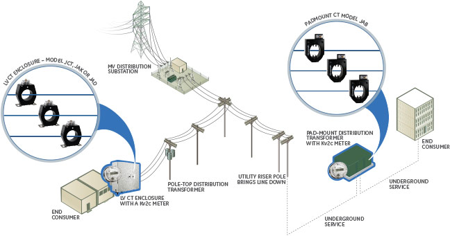
Application Overview: Secondary Metering with Current Transformers
Encompass and RevenueSense CTs provide flexibility for commercial and industrial applications, indoor or outdoor service and bar-type or window-type configurations.
Redefining Special High Accuracy
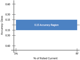
Per IEEE C57.13.6, a 0.15S class CT must maintain 0.15 accuracy from 5% of rated current through rating factor. This is a significantly tighter tolerance for error as compared to a standard CT: 2X better within rating factor and 4X better at light loads.
With GE Vernova’s RevenueSense CT’s, this tight tolerance of 0.15 accuracy is maintained for an extended range of 1% of rated current through rating factor. Similar to Encompass CT’s, moving from a standard CT to a wide range CT allows for a reduction in inventory, part numbers, and billing multipliers.
However, where Encompass CT’s offer equal performance over an extended range, RevenueSense CT’s offer improved high accuracy performance, allowing for increased billing accuracy and increased revenue.
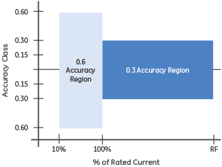
Standard CT Test Limits
RevenueSense Test Limits
Results and Benefits
The RevenueSense CT with rated range from 1% up through a rating factor of 3 covers the operating range of up to 8 other standard ratios, allowing for up to 90% reduction in inventory requirements. Additionally, the tolerance for CT error is tighter over the entire range, allowing for improved metering accuracy, particularly at light loads.

Business Case Example
In this business case example, a commercial customer requires premium accuracy to maximize billing revenue. The assumed hours of operation for this business are Monday to Friday, 9am to 5pm. The business is closed weeknights and weekends.
Assumptions:
- Nominal system with current of 200A
- System impedance of 0.1Ω
- Line to ground voltage of 277V vfactor of 0.9
- per kWh of $0.09
Load Conditions:
- Load is 100% of nominal current (200A) for 8 hours each weekday
- 10% of nominal current (20A) for 16 hours each weekday
- 5% of nominal current (2A) during weekends
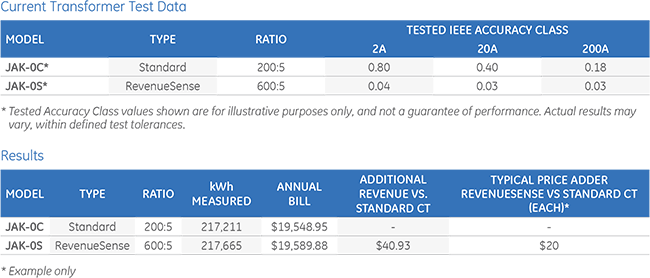
Results and Benefit
The RevenueSense CT, with its premium accuracy increases billing revenue by $40.93 annually versus the standard CT. The additional cost of three high accuracy CT’s is roughly $60 in this example, yielding a payback in less than 18 months.
Selector Guide
| Standard CT Make & Model | Ratios | Operating Range | GE Vernova RevenueSense Model | Ratio | Operating Range |
|---|---|---|---|---|---|
| GE Vernova JCR-0C or JCW-0C ABB CSF or CSH Ritz DCCW Itron R6M or R6SA GEC Durham TCW or TFW | 100:5, 200:5, 300:5, 400:5, 500:5, 600:5, 800:5 | 10A-1000A | JCT-0S | 600:5 | 6A-1200A |
| GE VERNOVA JAK-0C ABB CMF Ritz DCCW Itron R6M GEC Durham AB | 200:5, 300:5, 400:5, 500:5, 600:5, 800:5, 1200:5 200:5, 300:5, 400:5, 500:5, 600:5, 800:5, 1000:5, 1200:5, 2000:5 | 20A-1800A
20A-2000A | JAK-0S
JAK-0S | 600:5
1000:5 | 6A-1800A*
10A-2000A |
| GE VERNOVA JAB-0C ABB CMV Ritz DCDW Itron R6P GEC Durham AP | 200:5, 300:5, 300:5, 400:5, 500:5, 600:5, 1000:5 600:5, 800:5, 1000:5, 1200:5, 1500:5, 3000:5, 4000:5 | 20A-2000A
60A-4000A | JAB-0S
JAB-0S | 1000:5
2000:5 | 10A-2000A
20A-4000A |
| GE VERNOVA JAD-0C ABB CLC Ritz DCEW Itron R6L GEC Durham AD | 400:5, 500:5, 600:5, 800:5, 1000:5, 1200:5, 2000:5, 3000:5 600:5, 800:5, 1000:5, 1200:5, 1500:5, 2000:5, 3000:5, 4000:5 | 40A-4000A
60A-4500A | JAD-0S
JAD-0S | 2000:5
3000:5 | 20A-4000A
30A-4500A |
* JAK-0S also available with RF=2 with high burden
CT Models
Recommended Products & services

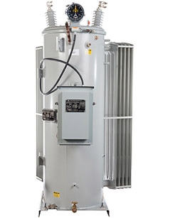
GE Vernova Transformers
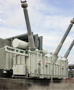
To utilities and industrials, GE Vernova's power and auto transformers are the product of choice because they deliver the reliability and performance required due to their design, manufacturing and support characteristics. These characteristics aid our customers in offering the best level of energy supply.
GE Vernova Transformers
To utilities and industrials, GE Vernova's power and auto transformers are the product of choice because they deliver the reliability and performance required due to their design, manufacturing and support characteristics. These characteristics aid our customers in offering the best level of energy supply.

GE Vernova Autotransformers

Step up Transformers

Substation & Auxilary Transformers
Recommended Products & services
Generator Step-up Transformers
GE Vernova’s generator step-up (GSU) transformers are designed and manufactured to...
View More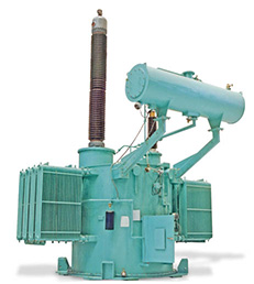
GE Vernova Transformers
To utilities and industrials, GE Vernova's power and auto transformers are the product of...
View More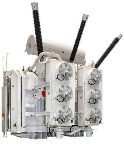
Power Transformers
GE Vernova’s comprehensive suite of power transformers support a wide range of voltage...
View MoreGenerator Step-up Transformers
GE Vernova’s generator step-up (GSU) transformers are designed and manufactured to stringent standards, providing superior performance and long life. They are suitable for nuclear, thermal and hydraulic applications from small to high voltages with power ratings from 5 MVA to 1000 MVA. The step-up transformers have delta-connected LV windings energized by the generator voltage, while star connected HV windings are connected to the transmission lines.
Generator Step-up Transformers
GE Vernova’s generator step-up (GSU) transformers are designed and manufactured to stringent standards, providing superior performance and long life. They are suitable for nuclear, thermal and hydraulic applications from small to high voltages with power ratings from 5 MVA to 1000 MVA. The step-up transformers have delta-connected LV windings energized by the generator voltage, while star connected HV windings are connected to the transmission lines.
Prolec GE Step-up Transformers
Recommended Products & services
Generator Step-up Transformers
GE Vernova’s generator step-up (GSU) transformers are designed and manufactured to...
View More
GE Vernova Transformers
To utilities and industrials, GE Vernova's power and auto transformers are the product of...
View More
Power Transformers
GE Vernova’s comprehensive suite of power transformers support a wide range of voltage...
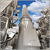
View MoreSPVL
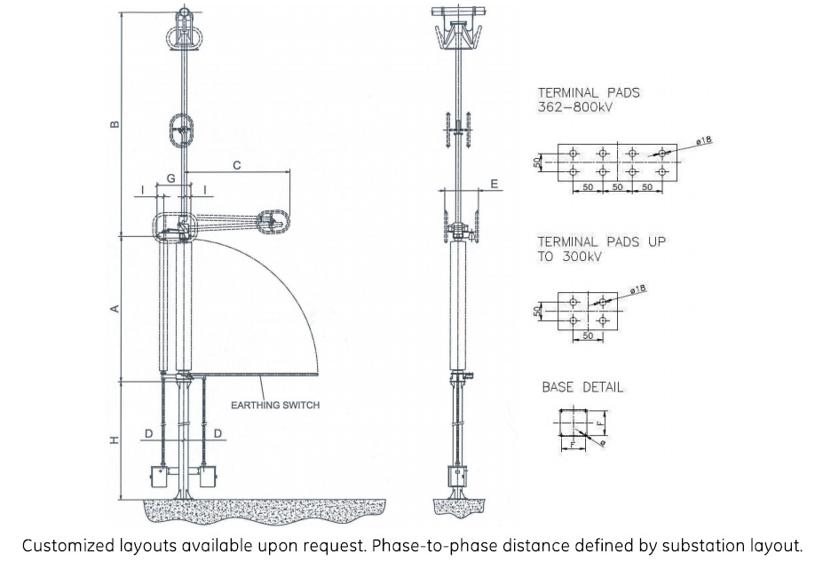
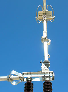
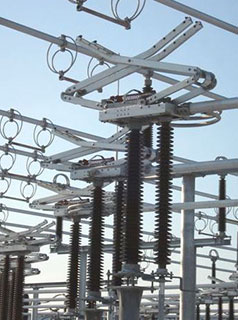
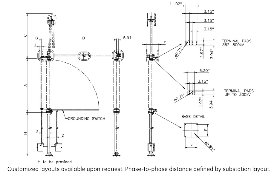
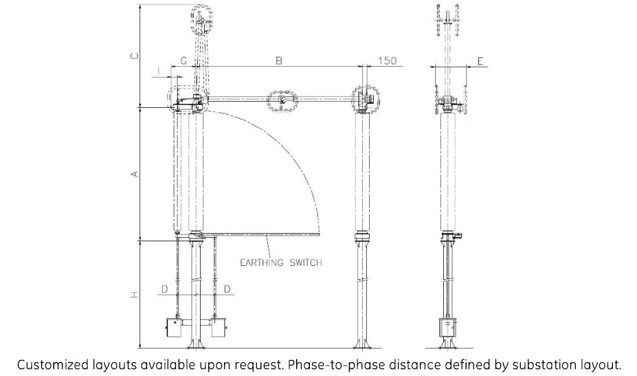
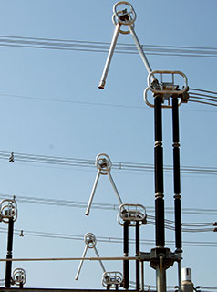
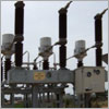
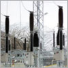
Semi-Pantograph Disconnector up to 1,000 kV
The SPVL is a space saving vertical reach disconnector connecting the lower busbar to the upper one via the semi-pantograph arm. Horizontal rather than vertical separation means a space reduction of as much as 30%. The SPVL is equipped with unique pollution and ice-free L-Contact.
SPVL
Semi-Pantograph Disconnector up to 1,000 kV
The SPVL is a space saving vertical reach disconnector connecting the lower busbar to the upper one via the semi-pantograph arm. Horizontal rather than vertical separation means a space reduction of as much as 30%. The SPVL is equipped with unique pollution and ice-free L-Contact.
- Flexible installation and arrangement configurations
- Unique L-contact design for switches used in heavily polluted or iced sites, and where extended mechanical endurance (10,000 operations) is required
- Blades are extra heavy, one piece, tubular aluminium with replaceable silver plated copper contacts at each end
- In open position, blade sections fold upon themselves, offering maximum dimension slightly greater than half the open gap dimension
- Clear busbar arrangement and routing results in increased safety during operation and maintenance
- Virtually maintenance free with factory-sealed bearings, life-time greased or self-lubricating parts and corrosion-free materials
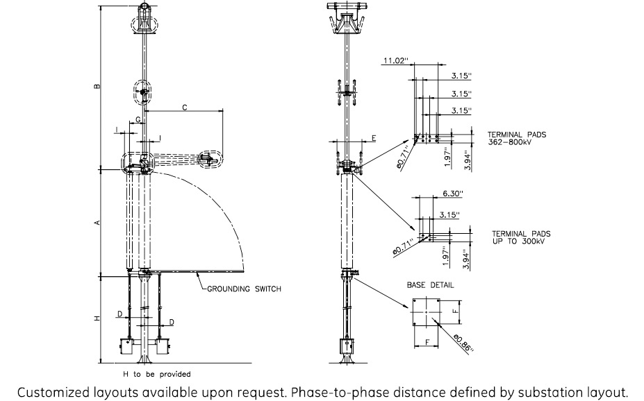
Specifications
Technical Data (IEC)
| Rated Voltage | Rated Current A/ Short time current kA | BIL kV | A inches | B inches | C inches | D inches | E inches | F inches | G inches | I inches |
|---|---|---|---|---|---|---|---|---|---|---|
| 145 kV | 4,000/80 | 650 | 5' 2 1/2" | 9' 10" | 4' 3 1/4" | 1' 4 3/4" | 1' 7 3/4" | 1' 1 1/2" | 2' 6" | 6 3/4" |
| 170 kV | 4,000/80 | 750 | 5' 10 1/4" | 9' 10" | 4' 3 1/4" | 1' 4 3/4" " | 1' 7 3/4" | 1' 1 1/2" | 2' 6" | 6 3/4" |
| 245R kV | 4,000/80 | 950 | 7' 4 1/4" | 13' 1 1/2" | 5' 7" | 1' 4 3/4" | 1' 7 3/4" | 1' 1 1/2" | 2' 6" | 6 3/4" |
| 245 kV | 4,000/80 | 1050 | 8' 4 1/4" | 13' 1 1/2" | 5' 7" | 1' 4 3/4" | 1' 7 3/4" | 1' 1 1/2" | 2' 6" | 6 3/4" |
| 362 kV | 4,000/80 | 1300 | 10' 7 1/4" | 15' 9" | 7' 8 1/2" | 1' 11 1/2" | 2' 7 1/2" | 1' 3 3/4" | 3' 3 1/4" | 7 3/4" |
| 550 kV | 4,000/80 | 1800 | 13'7 1/2" | 21' 11 3/4" | 8' 6 1/4" | 1' 11 1/2" | 3' 3 1/4" | 1' 3 3/4" | 3' 3 1/4" | 7 3/4" |
| 800 kV | 4,000/80 | 2050 | 17' 1 1/4" | 25' 11" | 12' 9 1/2" | 1' 11 1/2" | 1' 3 3/4" | 1' 3 3/4" | 3' 3 1/4" | 7 3/4" |
Drawings
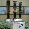
SPOL
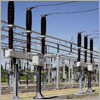
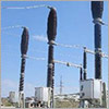
Knee Type Disconnector up to 1,200 kV
GE Vernova’s SPO is a vertical break disconnector with a two-piece arm. In the open position the blade sections fold upon themselves in a vertical plane of only 60% of the longitudinal dimension. The SPOL is equipped with the unique pollution and ice-free L-Contact and bus transfer contacts.
SPOL
Knee Type Disconnector up to 1,200 kV
GE Vernova’s SPO is a vertical break disconnector with a two-piece arm. In the open position the blade sections fold upon themselves in a vertical plane of only 60% of the longitudinal dimension. The SPOL is equipped with the unique pollution and ice-free L-Contact and bus transfer contacts.
- Unique L-contact design for switches used in heavily polluted or iced sites, and where extended mechanical endurance (10,000 operations) is required
- Substation crossing structures and wires can be lower and less expensive than conventional vertical break disconnectors
- Low center of gravity for live part provides high performance during earthquakes and faster, smoother and rebound-free operation
- Virtually maintenance free with factory-sealed bearings, life-time greased or self-lubricating parts and corrosion-free materials
Specifications
Technical Data (IEC)
| Rated Voltage | Rated Current A/ Short time current kA | BIL kV | A mm | B mm | C mm | D mm | E mm | F mm | G mm | I mm | Ø mm | ||
|---|---|---|---|---|---|---|---|---|---|---|---|---|---|
| 362 kV | 4000/63 | 1175 | 3190 | 3700 | 2500 | 600 | 800 | 400 | 800 | 200 | 26 | ||
| 420 kV | 4,000/63 | 1425 | 3640 | 4200 | 2700 | 600 | 800 | 400 | 800 | 200 | 26 | ||
| 550 kV | 4,000/63 | 1550 | 4290 | 5350 | 3500 | 600 | 1000 | 400 | 800 | 200 | 26 | ||
| 800 kV | 4,000/63 | 2100 | 5490 | 6000 | 3800 | 600 | 1100 | 500 | 800 | 200 | 34 | ||
Drawings
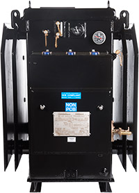
Safe-NET Network Transformers
Safely and reliably supply power to secondary grid systems
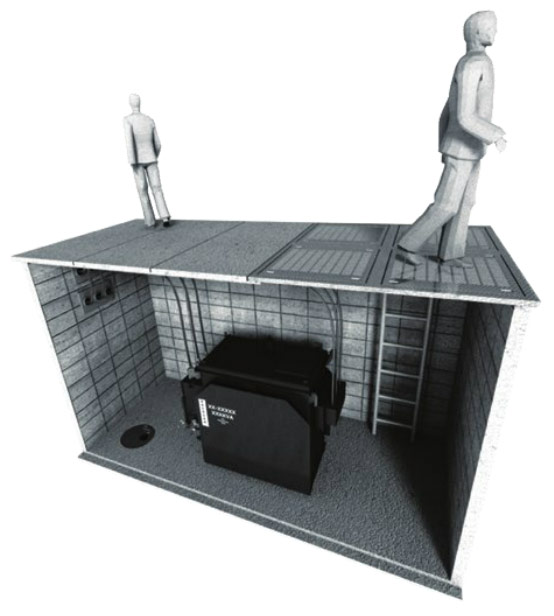
Utilities provide safe and reliable electrical service to their end customers. In large metropolitan areas with densely populated cities, utilities provide this service over secondary network distribution systems. These network systems are largely underground, therefore the network transformers that support these systems are a vital and critical part of the electrical infrastructure.
Safe-NET Network Transformers
Safely and reliably supply power to secondary grid systems
Utilities provide safe and reliable electrical service to their end customers. In large metropolitan areas with densely populated cities, utilities provide this service over secondary network distribution systems. These network systems are largely underground, therefore the network transformers that support these systems are a vital and critical part of the electrical infrastructure.

Network Transformer Overview
GE Vernova's Network Transformers offer utilities a solution that can help them provide safe, reliable and dependable electrical service to their end customers. GE Vernova's Network Transformer installed base includes units with 85+ years of service and giving utilities the peace of mind and operational assurance for their networks.
Network Transformer Portfolio
- 300-2500 KVA, 3 Phase
- Suitable for secondary networks and spot networks
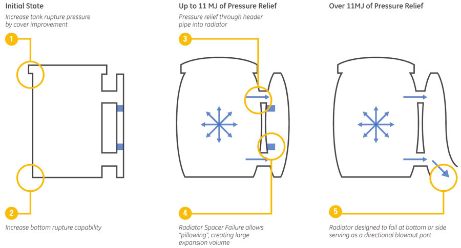
Patented Tank Technology
- Rupture resistant tank design allows for a safe and controlled sequence of events during high energy event. Exceeds the tank pressure requirements laid out in ANSI/IEEE C57.12.40 standard
Long Operational Life
- Safe-NET design evolved from products with 85+ years of service
- Tested and certified to the maximum (ground level) seismic levels in North America
- Corrosion resistant exterior
Superior Coil Design
- High short circuit strength
- Insulation system designed for increased loading capacity
Mechanical Strength
- Rugged clamping
- Safe lifting provisions
Industry Leader in Quality
- GE Vernova's Six-Sigma quality initiative ensures superiority in design and manufacturing
Key Differentiators for GE Vernova's Network Transformers
GE Vernova's provides customers with the safest network transformers for increased network operational safety than traditional design due to:
Exclusive Tank Design
- Patented tank technology provides a safe and controlled failure-mode during high energy events
- Exclusive transformer tank design and patented tank technology minimizes the danger from an "end-of-life" event resulting from a high-energy fault
- Best in class corrosion resistant paint minimizes maintenance over long haul and increases life cycle of transformer
Exceeds Industry Standards
- The Safe-NET tank design exceeds the tank pressure requirements laid out in the ANSI®/IEEE® C57.12.40 standard
- Patented tank design can contain most high energy events
- Best in class product lifecycle including an installed base with 85+ years of service
3rd Party Validated
- GE Vernova's units are capable of withstanding in excess of 11MJ of energy, confirmed by KEMA® testing
- Tested and certified to the highest North American standard for ground-level seismic levels, CBC-2013 section 1705A.12 and IBC 2012 section 1705.12, tested to (an acceleration value of) SDS = 2.5
- Superior zinc epoxy primer and black epoxy top coat paint with 10,000 hour salt-spray certification
Controlled High Energy Tank Design Sequence
Application Overview
GE Vernova's Safe-NET Network Transformers are used in applications where safety, reliability, service continuity and minimum maintenance are the key objective including:
- Underground metropolitan vault applications
- Government, commercial, institutional and industrial facilities
- Office towers, skyscrapers
- Vault applications with occasional/continuous submersion
Safe-NET can also be applied to non-network applications where superior sealing and corrosion protection are of primary importance. These non-network applications also include intertie [step] transformers for interconnecting two different voltage systems.
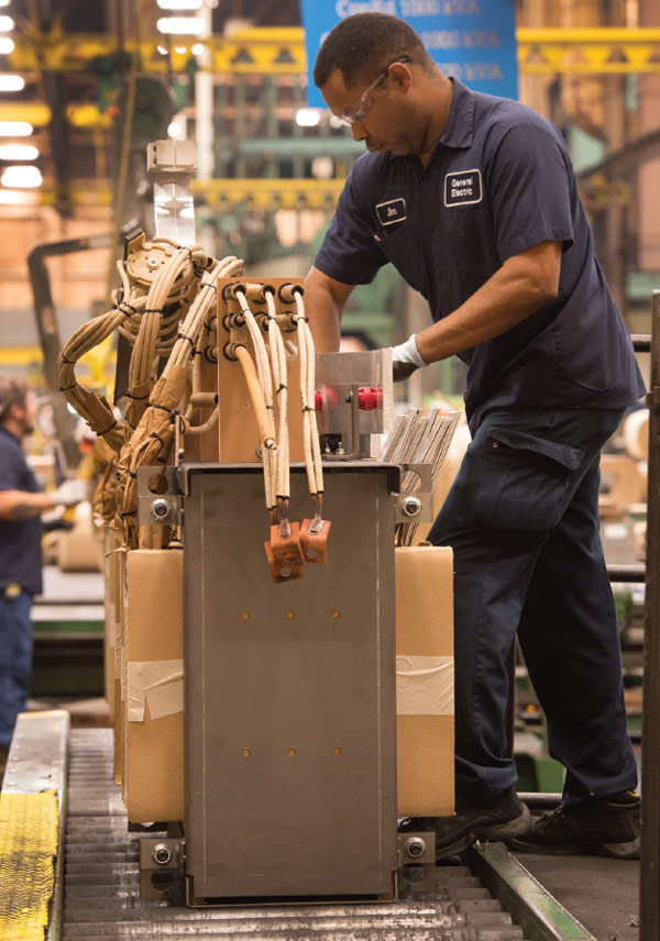 Assembly of Interior cabling and barwork
Advanced Technology and Manufacturing
State-of-the-art 600,000 square-foot manufacturing facility comprised of operations such metal fabrication, welding, core assembly, and coatings. The manufacturing site is ISO 9001 certified and conducts quality inspections for purchased and outsourced materials. The manufacturing facility is located in Shreveport, LA and serves customers around the world.
Exceptional Quality and Reliability
- ISO 9001 certified processes
- ANSI compliant products available
- 3rd party product certifications
- Multiple checkpoints in the production, assembly and inspection process
- Rigorous electrical, oil quality, and leak testing
- Special testing such as heat run and sound tests with reporting capability available
- On-site GE Vernova quality engineers and technicians
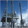
Live Tank Circuit Breakers up to 800 kV
The GL series is safer and more reliable that previous circuit breakers designs. It offers a new generation of spring-spring operating mechanism that enables quick and easy onsite installation.
This range of Live Tank Circuit Breakers can be used everywhere in the energy field even in highly seismic, highly polluted and low temperature environments. The breakers benefit from single and three pole application and their low energy operation makes them a cost-effective option.
GL 107X
Live Tank Circuit Breaker from 36 kV up to 40.5 kV
GL 308 and GL 309
Live Tank Circuit Breakers for 52 kV and 72.5 kV
GL 309g, GL 310g, GL 311g and GL 312g
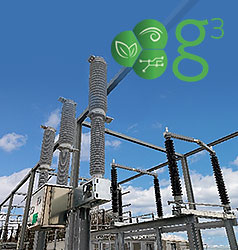
g³ live tank circuit breakers from 72.5 kV up to 145 kV

GL 309c, GL 310c, GL 311c and GL 312c
SF₆-free Live Tank Circuit Breakers
From 72.5 kV to 145 kV down to -50 °C
GL 310 S, GL 311 S and GL 312 S
Live Tank Circuit Breakers from 100 kV to 145 kV
Down to -30 °C with pure SF₆
GL 310, GL 311 and GL 312
Live Tank Circuit Breakers from 100 kV to 145 kV
Down to -40 °C with pure SF₆ and - 60 °C with gas mixture
GL 313
Live Tank Circuit Breaker from 145 kV up to 170 kV
GL 314 and GL 314X
Live Tank Circuit Breakers up to 245 kV and 300 kV
GL 314 BPS
Live Tank Circuit Breaker By-Pass-Switch up to 245 kV
GL 315 and GL 315X
Live Tank Circuit Breakers up to 362 kV
GL 316 and GL 316X
Live Tank Circuit Breakers up to 420 kV
GL 317 and GL 317X
Live Tank Circuit Breakers up to 550 kV
GL 318 and GL 318X
Live Tank Circuit Breakers up to 800 kV
Recommended Products & services
GL309c, GL310c, GL311c, GL312c
Your SF₆-free solution to reduce carbon footprint More and more electrical grid...
View More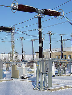
Live Tank Circuit Breakers up to 800 <span class="text-lowercase">k</span>V
The GL series is safer and more reliable that previous circuit breakers designs. It...
View More
GL 315 / GL 315X
Reliable, Economical and Easy-to-Use GE Vernova’s GL 315 and GL 315X live tank circuit...
View MoreLine Traps
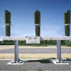
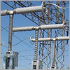
Light Weight, Flexible Mounting
Line traps are used in transmission and distribution networks around the world. Line traps are a key component in PLC (Power Line Carrier) systems used for remote control signals, voice communication, remote metering and control between substations in the electrical T&D network.
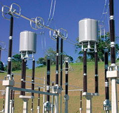
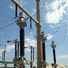
Line Traps
Light Weight, Flexible Mounting
Line traps are used in transmission and distribution networks around the world. Line traps are a key component in PLC (Power Line Carrier) systems used for remote control signals, voice communication, remote metering and control between substations in the electrical T&D network.
Characteristics
- Up to 800 kV
- Up to 5,000 A
- 30-500 kHz frequency range
- High short-circuit withstand capability
- Mounting flexibility: vertical, horizontal or suspension
- Extremely reliable tuning devices
- Self-resonnance frequency greater than 500 kH
- Fixed or adjustable tuning devices
- Excellent cooling capabilities
- Maintenance free
- Air core, dry type
- Outdoor use
- Complaint with IEC and IEEE or equivalent standard
Specifications
| I (A) | Standard | Isc (kA) / 1s | Isc (kApeak) | L (mH) | |||||
|---|---|---|---|---|---|---|---|---|---|
| 400 | IEC I | 10 | 25.5 | 0.1 | 0.2 | 0.32 | 0.5 | 1.0 | 2.0 |
| IEC II | 16 | 41 | 0.1 | 0.2 | 0.32 | 0.5 | 1.0 | 2.0 | |
| 630 | IEC I | 16 | 41 | 0.1 | 0.2 | 0.32 | 0.5 | 1.0 | 2.0 |
| IEC II | 20 | 51 | 0.1 | 0.2 | 0.32 | 0.5 | 1.0 | 2.0 | |
| 800 | IEC I | 20 | 51 | 0.1 | 0.2 | 0.32 | 0.5 | 1.0 | 2.0 |
| IEC II | 25 | 64 | 0.1 | 0.2 | 0.32 | 0.5 | 1.0 | 2.0 | |
| 1250 | IEC I | 31.5 | 80.5 | 0.1 | 0.2 | 0.32 | 0.5 | 1.0 | 2.0 |
| IEC II | 40 | 102 | 0.1 | 0.2 | 0.32 | 0.5 | 1.0 | 2.0 | |
| 1600 | IEC I | 40 | 102 | 0.1 | 0.2 | 0.32 | 0.5 | 1.0 | 2.0 |
| IEC II | 50 | 127.5 | 0.1 | 0.2 | 0.32 | 0.5 | 1.0 | 2.0 | |
| 2000 | IEC I | 40 | 102 | 0.1 | 0.2 | 0.32 | 0.5 | 1.0 | 2.0 |
| IEC II | 50 | 127.5 | 0.1 | 0.2 | 0.32 | 0.5 | 1.0 | 2.0 | |
| 2500 | IEC I | 40 | 102 | 0.1 | 0.2 | 0.32 | 0.5 | 1.0 | 2.0 |
| IEC II | 50 | 127.5 | 0.1 | 0.2 | 0.32 | 0.5 | 1.0 | 2.0 | |
| 3150 | IEC I | 40 | 102 | 0.1 | 0.2 | 0.32 | 0.5 | 1.0 | 2.0 |
| IEC II | 50 | 127.5 | 0.1 | 0.2 | 0.32 | 0.5 | 1.0 | 2.0 | |
| 4000 | IEC I | 63 | 161 | 0.1 | 0.2 | 0.32 | 0.5 | 1.0 | 2.0 |
| IEC II | 80 | 204 | 0.1 | 0.2 | 0.32 | 0.5 | 1.0 | 2.0 | |
| * Shaded rating not available with OSD | |||||||||
Line traps according to ANSI standard
| I(A) | Standard | Isc (kA) / 2s | Isc (kA peak) | L (mH) |
|---|---|---|---|---|
| 400 | ANSI | 15 | 38.5 | 0.265 |
| 800 | ANSI | 20 | 51 | 0.265 |
| 1200 | ANSI | 36 | 91.8 | 0.265 |
| 1600 | ANSI | 44 | 112 | 0.265 |
| 2000 | ANSI | 63 | 161 | 0.265 |
| 3000 | ANSI | 63 | 161 | 0.265 |
| 4000 | ANSI | 80 | 204 | 0.265 |
| 5000 | ANSI | 80 | 204 | 0.265 |
| Other rating can be designed upon request. | ||||
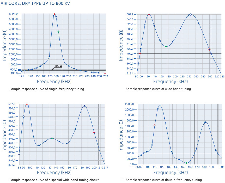
Frequency Tuning
Recommended Products & services
Line Traps
Light Weight, Flexible Mounting Line traps are used in transmission and distribution...
View MoreHigh Voltage Instrument Transformers
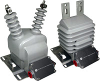
Instrument Transformers are an essential link for the safe and efficient operation of transmission networks. They provide accurate and reliable current and voltage measurements for secondary equipment such as meters, protections relays, bay computers and other devices.
GE Vernova has manufactured tens of thousands high voltage instrument transformers. Our customers recognize our top-of-the-line products for their long term robustness, safety and reliability.
High Voltage Instrument Transformers
Instrument Transformers are an essential link for the safe and efficient operation of transmission networks. They provide accurate and reliable current and voltage measurements for secondary equipment such as meters, protections relays, bay computers and other devices.
GE Vernova has manufactured tens of thousands high voltage instrument transformers. Our customers recognize our top-of-the-line products for their long term robustness, safety and reliability.
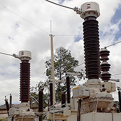
OSKF Oil-Insulated Current Transformers up to 800 kV
GE Vernova’s OSKF have been designed for a 30-year lifetime and, thanks to the profound technical concepts, many well out-live this service life. The oil is hermetically sealed from the air by a stainless-steel diaphragm assembly and all external parts are of corrosion-resistant material.
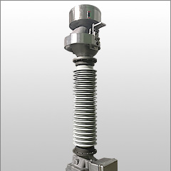
OTEF Oil-Insulated Voltage Transformers up to 420 kV
GE Vernova manufactures a complete range of high voltage oil-filled voltage transformers (VTs). The OTEF is a tank-type potential transformer with post insulator. Thousands voltage transformers are in service worldwide, in all types of climates and under the most severe conditions.
KOTEF Oil-Insulated Combined CT/VT up to 420 kV
KOTEF utilizes the same components as the individual CTs and VTs. Both transformers are combined in a single metering unit and are available in porcelain or composite. The KOTEF combines the advantages and design features of the OSKF and OTEF lines.
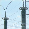
OTCF Coupling Capacitor Voltage Transformers up to 800 kV
In high and extra high voltage transmission systems, capacitor voltage transformers (CVTs) are used to provide potential outputs to metering instruments and protective relays. In addition, when equipped with carrier accessories, CVTs can be used for power line carrier (PLC) coupling.
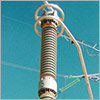
CCV Capacitor Voltage Transformers and CC Coupling Capacitors up to 800 kV
In high and extra high voltage transmission systems, capacitor voltage transformers (CVTs) are used to provide potential outputs to metering instruments and protective relays. In addition, when equipped with carrier accessories, CVTs can be used for power line carrier (PLC) coupling.
Recommended Products & services
High Voltage Instrument Transformers
Instrument Transformers are an essential link for the safe and efficient operation of...
View MoreCircuit Breaker Retrofit
For Gas-Insulated Substation
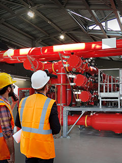
GE Vernova’s GIS retrofit solutions are designed to replace aging or obsolete circuit breakers manufactured by GE Vernova or a 3rd party with a new GE Vernova circuit breaker that includes the pure spring mechanism.
The GIS retrofit solution is a cost effective and reliable method to modernize and extend the lifetime of the substation by gaining all the advantages of implementing new reliable technology.
The solution is suitable to replace vertical or horizontal GIS circuit breakers.
The turnkey service solution includes:
Circuit Breaker Retrofit
For Gas-Insulated Substation
GE Vernova’s GIS retrofit solutions are designed to replace aging or obsolete circuit breakers manufactured by GE Vernova or a 3rd party with a new GE Vernova circuit breaker that includes the pure spring mechanism.
The GIS retrofit solution is a cost effective and reliable method to modernize and extend the lifetime of the substation by gaining all the advantages of implementing new reliable technology.
The solution is suitable to replace vertical or horizontal GIS circuit breakers.
The turnkey service solution includes:
Main Characteristics
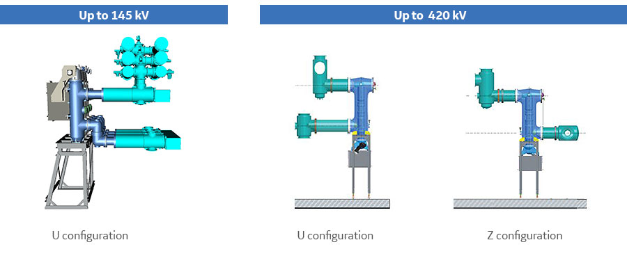
GE Vernova’s solution is designed for 72.5-145 kV and 300 kV-420 kV gas-insulated substations, regardless of the manufacturer or the application. To match the existing configuration and dimensions, phase-distance can be adapted with the interface and the 420 kV circuit breaker can be installed in U or Z configuration.
Vertical Circuit Breaker with Pure Spring Mechanism
The vertical circuit breakers proposed to retrofit the gas-insulated substation are equipped with the pure spring mechanism used in all GE Vernova HV circuit breakers. This proven technology enables minimized maintenance and improved reliability. Key features include:
- Single-phase enclosure ensures safe operation with all moving parts fully encapsulated
- Gas compartment is up to 50% smaller compared to the previous generation
- Low closing and tripping force is required reducing the need for energy to trigger the switching
- Low static and dynamic forces reduce the mechanical constraints and stress during operation, resulting in increased asset reliability
- Single chamber design lowers the number of moving parts and the energy required
- All models are type tested
- A RPH3 point of wave controller can be added to the solution to synchronize the phases for switching
GE Vernova Advantage
Versatile Solution
- Suitable for all brands of GIS
- Different configurations available to fit with existing architecture
- Compact footprint with vertical arrangement
Reliable Technology
- Up to 42% reduction in unplanned outage risk, due to pure spring operating mechanism
- Up to 22% reduction in outage duration due to “plug and play” solution
Safe and Eco-friendly
- 50% reduction in SF6 mass
- Reduced risk of leakage by 10 times
- 25% reduction in required material including copper, aluminum and gasket
Cost Effective Solution
- Up to 60% reduction in maintenance costs due to pure spring mechanism compared to pneumatic or hydraulic technology
- Reduced investment cost and outage time compared to a GIS replacement
Vertical Circuit Breaker Specifications
| Breaker Type | 145 kV Vertical | 420 kV Vertical |
|---|---|---|
| Reference electro-technical standards | IEC/IEEE | |
| Rated voltage | 145 kV | 420 kV |
| Rated frequency | 50/ 60 Hz | |
| Enclosure | Single-phase | |
| Short-duration power-frequency, phase-to-earth/across isolation distance | 275 kV /315kV | 520/610 kV |
| Lightning impulse phase-to-earth/across isolation distance | 650 kVp / 750 kVp | 1425/1425 (+240) kVp |
| Rated current | up to 3150 A | up to 5000 A |
| Rated peak withstand current | 100 kAp / 108 kAp | 170 kAp |
| Rated short-time current | 40/3 kA/s | 63/3 kA/s |
| Rated short circuit breaking current | 40 kA | 63 kA |
| First-pole-to-clear factor | 1.5 | 1.3-1.5 |
| SF6 weight / pole | 5.4 kg | 50 / 60 kg |
| Operating sequence | O – 0.3s – CO – 3 min – CO CO – 15s - CO | |
| Min. gas operating pressure at 20°C (50Hz) | 5.5 bar | 5.5 bar |
| Circuit breaker approx. weight | 1500 kg | 4230 kg |
Recommended Products & services
Circuit Breaker Retrofit
GE Vernova’s GIS retrofit solutions are designed to replace aging or obsolete circuit...
View More