
Event: Test ICS File
Date: From Thursday, November 21, 2024 to Friday, November 22, 2024
Time: 9 am to 6 pm
Location: Bangalore, India
If you require more information regarding this event please contact: Udhay

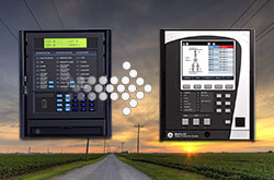
Manufacturing for 489 has been discontinued. As an alternative, please refer to the 889 relay.
Manufacturing for 489 has been discontinued. As an alternative, please refer to the 889 relay.
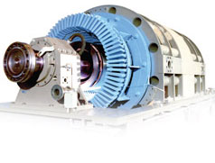
The 489 Generator Protection System provides comprehensive protection, metering, and monitoring of small to medium sized synchronous or induction generators operating at 25, 50 or 60 Hz. The 489 is ideally suited for primary or backup generator protection as well as for use in cogeneration applications. Protection features found in the 489 include:
 Analyze generator faults using waveforms that are captured at the time of generator faults or system instabilities
The 489 offers a multitude of different analog and digital inputs and outputs to allow the 489 to be seamlessly integrated into most generator automation schemes.
The 489 provides six output contacts for the purpose of controlling or signaling other devices and operations personnel. Protection elements can be configured to control the Trip contact, the Alarm contact, or the 3 Auxiliary contacts whenever the element operates. The status of each of these contact are also displayed on LEDs found on the relays front panel.
Eight digital inputs are available for monitoring the status of external contacts, tachometers, or control switches. With these inputs, the relay can identify the status of the associated breakers and receive commands from operational staff such as controlling the output relays, resetting the thermal limits, or triggering a waveform capture.
Twelve RTD inputs allow the 489 to monitor both the generator stator and bearing temperature. A built in voting feature adds additional security by ensuring that two RTDs monitoring the same device both detect the overtemperature condition before tripping the generator offline.
Four analog inputs are available for providing protection and monitoring of generator bearing vibration. The analog inputs are field programmable to measure transducer signals that operator over a range of 0 to 1 mA, 0 to 20 mA, or 4 to 20 mA.
Four analog outputs are available for signaling the value of measured analog quantities to external process control devices such as PLCs. The analog outputs can be ordered to operate over a 4 to 20mA range or a 0 to 1mA range and can be configured to signal a representation of most analog quantities measured by the 489 including currents, voltages, frequency.
The 489 provides advanced communications technologies for remote data and engineering access, making it easy and flexible to use and integrate into new or existing monitoring and control systems. Multiple communication ports are available including a front panel RS232 serial port for easy local computer access, two RS485 serial ports and a 10Mbps copper Ethernet port that provide direct integration in most communications architectures.
The 489 supports the most popular industry standard protocols enabling easy, direct integration into most DCS and SCADA systems. Protocols supported include:
The EnerVista™ Suite is an industry-leading set of software programs that simplify every aspect of using the 489 relay. The EnerVista™ suite provides all the tools to monitor the status of your protected asset, maintain the relay and integrate information measured by the 489 into DCS or SCADA monitoring systems. Convenient COMTRADE and Sequence of Events viewers are an integral part of the 489 Setup software included with every relay to carry out postmortem event analysis.
Learn More![]()
 Explore the 8 Series Retrofit Kit
Traditionally, retrofitting an existing relay has been a challenging, time consuming task often requiring re-engineering, new drawings, panel modifications, re-wiring and re-testing.
The 8 Series Retrofit Kit provides a quick, 3-step solution to upgrade previously installed SR 489 relays. With the new 8 Series Retrofit Kit users are able to install the 889 Generator Management System without modifying existing cutouts and wiring, and without any drawing changes or re-engineering time.
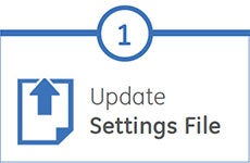
EnerVista 8 Series Setup Software provides automated setting file conversion. Once completed, a graphical report is provided to verify and call out any specific settings that may need attention.
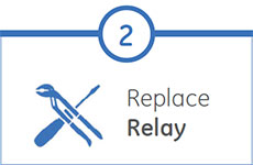
Simply remove the upper, lower and low voltage terminal blocks and then remove the SR chassis from the panel. No need to disconnect any of the field wiring.
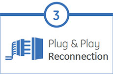
Insert the new 8 Series Retrofit chassis into the switchgear and simply plug-in the old terminal blocks - there is no need to make any cut-out modifications or push and pull cables.
GE Vernova's generator protection devices provide innovative solutions for the...
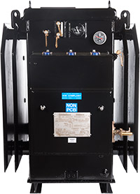
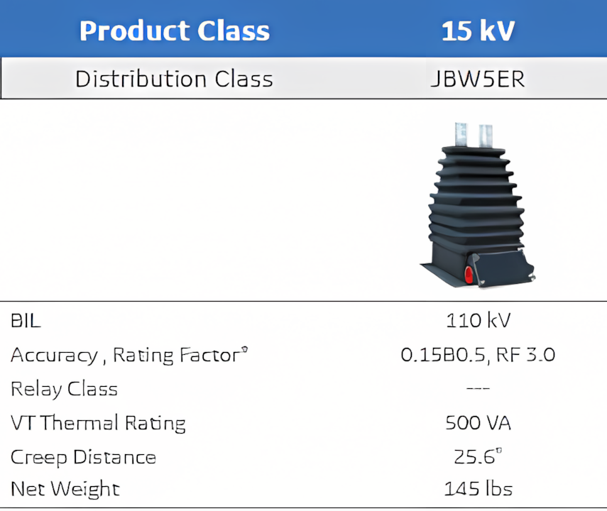
View MoreSUPERBUTE dry-type instrument transformers are engineered and rigorously tested to provide a measurable difference in reliability and durability. Since the very first unit produced in 1955, SUPERBUTE instrument transformers have provided utilities with a number of benefits for enhanced safety and a lower total cost of ownership. SUPERBUTE is designed to meet IEEE C57.13 standards and ANSI standard mounting provisions, terminals, and construction.
SUPERBUTE dry-type instrument transformers are engineered and rigorously tested to provide a measurable difference in reliability and durability. Since the very first unit produced in 1955, SUPERBUTE instrument transformers have provided utilities with a number of benefits for enhanced safety and a lower total cost of ownership. SUPERBUTE is designed to meet IEEE C57.13 standards and ANSI standard mounting provisions, terminals, and construction.
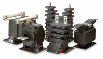 Distribution class SUPERBUTE offers compact designs for more efficient application to solid-state metering and other modern installations.
 Station class SUPERBUTE offers higher burden, higher thermal rating, and extra creep distance for substations or installations where higher ratings are required.
Field studies and accelerated life testing has shown an average operating life of more than 40 years, with reliability measures 3 times better than published industry benchmarks
Internal insulation is made from epoxy resin which is encapsulated in tough, elastic butyl rubber, dampening and minimizing the impact of high energy events
Unique dry-type construction ends oil leakage problems, eliminates breakage and vandalism issues, and does not support combustion
The dry-type design eliminates the need for oil testing or filtering and allows for a compact design which facilitates mounting flexibility for more economical installations such as on existing steel structures, inside a cabinet, or on a pole
Extensive vertical integration within the factory allows for standard lead times of 4-6 weeks, nearly half the industry average
 GE Vernova’s proprietary formula of non-arc tracking butyl rubber showed no carbonization after 4,000 hours in salt-fog testing, compared to standard butyl rubber which failed after 107 hours or standard porcelain which failed after 400 hours under the sa
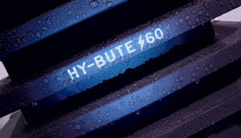
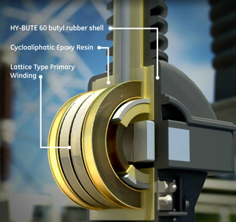
The outer shell of SUPERBUTE transformers are made with GE Vernova’s proprietary formula of butyl rubber, which is called HY-BUTE 60. This material adds the following timeless advantages over epoxy resins or porcelains designs:
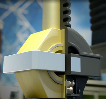 Cross section of a JVS350 station-class voltage transformer showing Epoxy encapsulated with HY-BUTE 60 butyl rubber shell
Epoxy takes the place of oil as the internal insulation and winding impregnation. The advantage of this design includes:
SUPERBUTE instrument transformers are designed for quality and reliability with features engineered to withstand high voltage stresses and extreme environmental conditions, while delivering the highest accuracies possible, all within a compact design. The result is a reliable, long-lasting, easy to handle design that ultimately lowers total cost of ownership.
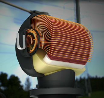
 Lattice-type winding in a JVS350 station-class VT
 Multi-gap type primary in a JKW350 station-class CT
Originally patented by GE Vernova, lattice-type windings have precise controlled positioning and distribution of each turn to reduce maximum voltage stress within the winding. This unique design also minimizes the possibility of partial discharges within the winding. The coil configuration, and the outer electrostatic shields distribute steep voltage fronts across the coil to reduce concentration of stress.
A unique multi-gap type primary by-pass on current transformers 600 amps and below protects windings during line disturbances or steep current wave fronts. The gaps are factory adjusted to fire at 5000-7500 crest volts, thereby by-passing surge currents up to 100 times rated, which could otherwise result in excessive voltages across the primary winding.
The use of high accuracy instrument transformers with solid-state metering allows for improved billing accuracy and/or the potential to reduce inventory requirements. GE Vernova offers high accuracy and extended range ratings which meet the accuracy needed for these applications. Since introducing the first dry-type high-accuracy transformer solution in 1991, GE Vernova’s high accuracy product line has grown to a portfolio that includes a wide variety of voltage classes up to and including 69 kV.
SUPERBUTE transformers require up to 30% less height and up to 40% less floor space compared to the leading oil-filled designs, and can be mounted in any position. This allows substation design flexibility including mounting on a substation steel structure or a pole.
Even with 30% less height, standard units can be used in environmentally severe conditions and in high altitude (10,000ft) applications. Station class units have creep distances that exceed the requirements for even the next-level voltage class.
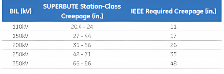 SUPERBUTE station-class creepage distances versus IEEE C57.13-2008 required levels, by system voltage
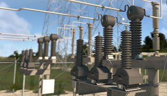
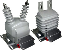
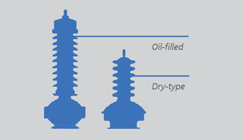 SUPERBUTE transformers are more compact and lower profile compared to the lead liquid filled transformers
Outdoor Voltage Transformers: Outdoor voltage transformers are available at 5-69 kV and 60-350 kV BIL. These units are offered in two distinct sizes for efficient sizing:
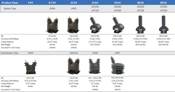
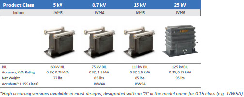
Indoor Voltage Transformers: Indoor Voltage Transformers are available at 5-25 kV system voltage and 60-200 kV BIL.
Outdoor Current Transformers: Outdoor current transformers are available in Bar-Type and Window-Type styles, 5-15 kV, 60 kV-110 kV BIL, up to 4000 A. Outdoor wound-type current transformers (CTs) are available 5-69 kV, 60-350 kV BIL, up to 1200 A. Wound-type units are available in two distinct sizes:
Outdoor current transformers are also available in Bar-Type and Window-Type styles, 5-15 kV, 60 kV-110 kV BIL, up to 4000A.
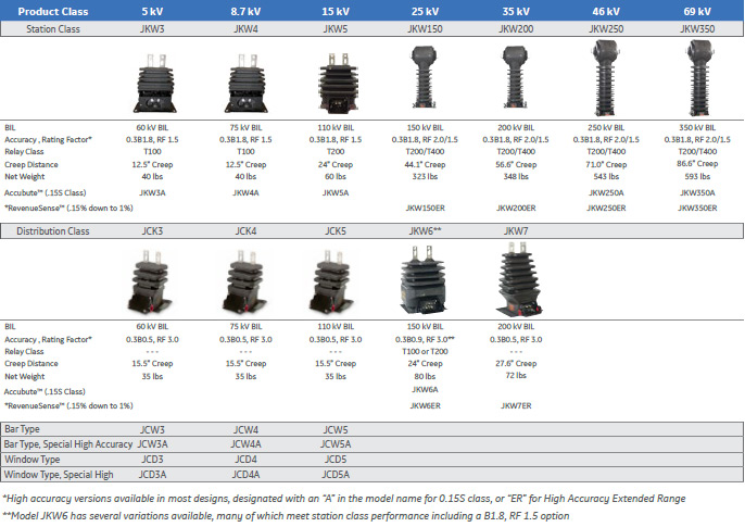
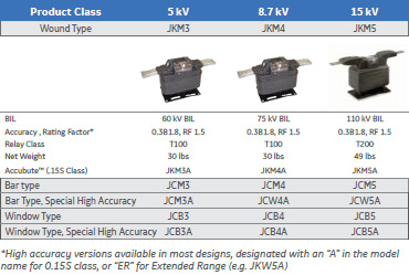
Indoor Current Transformers: Indoor current transformers are available 5-15 kV system voltage and 60-150 kV BIL. Product types include wound type up to 1200 A, and window-type or bar-type up to 4000 A.
Outdoor CT/VT combo: Designed for outdoor service, a combination voltage transformer (VT) and current transformer (CT) is typically used for primary metering applications. GE Vernova’s RevenueSense™ CT design provides 0.15 accuracy from 1% of rated current through rating factor.

MV outdoor instrument transformers insulated with Hydrophobic Cycloaliphatic Epoxy (HCEP)...
View More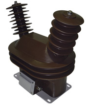
Instrument transformers perform a critical role in the management of power delivery...
View MoreThis range of voltage transformers is designed for applications up to 34.5 kV class with BIL ratings up to 200 kV. The core and coil assemblies are vacuum cast using polyurethane resin to provide high dielectric strength and rugged construction.
To review a list of specifications, click here
This range of voltage transformers is designed for applications up to 34.5 kV class with BIL ratings up to 200 kV. The core and coil assemblies are vacuum cast using polyurethane resin to provide high dielectric strength and rugged construction.
To review a list of specifications, click here
MV outdoor instrument transformers insulated with Hydrophobic Cycloaliphatic Epoxy (HCEP)...
View More
Instrument transformers perform a critical role in the management of power delivery...
View MoreThis range of polyurethane encapsulated current transformers is designed for 5 to 34.5 kV class applications. Several models may be ordered with or without primary bars to suit customers needs.
This range of polyurethane encapsulated current transformers is designed for 5 to 34.5 kV class applications. Several models may be ordered with or without primary bars to suit customers needs.
MV outdoor instrument transformers insulated with Hydrophobic Cycloaliphatic Epoxy (HCEP)...
View More
Instrument transformers perform a critical role in the management of power delivery...
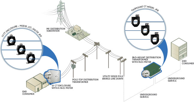
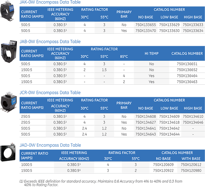
View MoreEncompass™ Current Transformers from GE Vernova offer electrical utilities piece of mind knowing they’ll have the right CT in stock. Upgrade today and eliminate the need for multiple current ratios, thereby simplifying CT selection.
Encompass wide range CTs are designed for commercial and industrial applications. Encompass CT’s substantially reduce inventory, complexity and improve standardization for meter shop operations, particularly when used with GE Vernova’s kV2c FITZALL™ transformer rated meters.
Encompass™ Current Transformers from GE Vernova offer electrical utilities piece of mind knowing they’ll have the right CT in stock. Upgrade today and eliminate the need for multiple current ratios, thereby simplifying CT selection.
Encompass wide range CTs are designed for commercial and industrial applications. Encompass CT’s substantially reduce inventory, complexity and improve standardization for meter shop operations, particularly when used with GE Vernova’s kV2c FITZALL™ transformer rated meters.
Encompass and RevenueSense CTs provide flexibility for commercial and industrial applications, indoor or outdoor service and bar-type or window-type configurations.
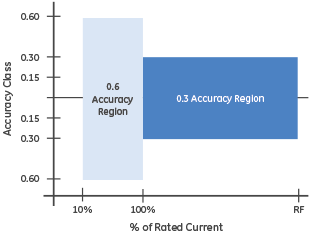
Traditionally, CT accuracy is tested at:
With GE Vernova Encompass CT’s, the 0.3 accuracy class is extended by changing the test points to:
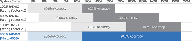
A rating factor of 4.0 means the Current Transformer meets rated accuracy at up to 4 times the rated primary current. Thus, the output on a 5 Amp CT secondary can be used up to 20 Amps if a rating factor of 4.0 is assigned to the CT (4.0*5A = 20A). This pairs the CT output range and the Meter input range when used with a CL20 transformer rated meter, maximizing the performance potential of the system.
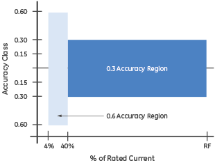
The 4% and 40% test points in combination with a high rating factor of 4.0 means 1 Encompass CT can equal or better the performance of both higher AND lower ratios.
The 500:5 Encompass unit when compared to a 200:5 standard CT has equal to or better test results at all points included even low currents and is available at an equivalent price. This comparison holds true across several other standard CT ratios, meaning one Encompass CT can functionally replace up to eight other standard ratios, allowing for an inventory reduction of up to nearly 90%.
To demonstrate the advantages of upgrading to an Encompass CT,
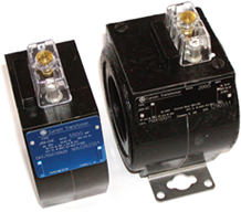
let’s compare a JAK-0W 500:5 Encompass CT to a JAK-0C 200:5 standard CT
Physically, the JAK-0W 500:5 Encompass CT:
Electrically, the accuracy of a JAK-0W 500:5 is equivalent or better than the accuracy of a JAK-0C 200:5 across all test points. This can be looked at two ways:
A 500:5 Encompass CT has ±0.3% accuracy from 200A to 2000A, compared to a standard 200:5 CT which has a ±0.3% accuracy from 200A to only 800A. Both CT’s have ±0.6% accuracy from 20A to 200A.

The 500:5 Encompass CT has equal to or better accuracy rating across the entire 20A to 2000A range. It is important to note that accuracy class only defines the “tolerance of error” allowed in a CT. Actual test results are also an important factor when evaluating CT’s. At a typical burden of B-0.1, the Encompass CT test results slightly outperform a standard CT, even at the lowest test amps. All Encompass test results are well within the IEEE limits.
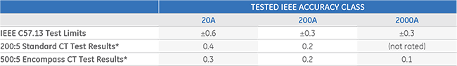
* Tested Accuracy Class values shown are for illustrative purposes only, and not a guarantee of performance. Actual results may vary, within defined test tolerances.
| Standard CT Make & Model | Ratios | Operating Range | GE Vernova Encompass Model | Ratio | Operating Range |
| GE Vernova JCR-0C or JCW-0C ABB CSF or CSH Ritz DCCW Itron R6M or R6SA GEC Durham TCW or TFW | 100:5, 200:5, 300:5, 400:5, 500:5 | 10A-1000A | JCR-0W | 250:5 | 10A-1000A |
| GE VERNOVA JAK-0C ABB CMF Ritz DCCW Itron R6M GEC Durham AB | 200:5, 300:5, 400:5, 500:5, 600:5, 800:5, 1000:5, 1200:5, 2000:5 | 20A-2000A | JAK-0W | 500:5 | 20A-2000A |
| GE VERNOVA JAB-0C ABB CMV Ritz DCDW Itron R6P GEC Durham AP | 200:5, 300:5, 300:5, 400:5, 500:5, 600:5, 1000:05 | 20A-2000A | JAB-0W | 500:5 | 20A-2000A |
| 600:5, 800:5, 1000:5, 1200:5 | 60A-2400A | JAB-0W | 1500:5 | 60A-3000A | |
| GE VERNOVA JAD-0C ABB CLC Ritz DCEW Itron R6L GEC Durham AD | 2400:5, 500:5, 600:5, 800:5, 1000:5, 1200:5, 2000:5, 3000:5 | 40A-4000A | JAD-0W | 1000:5 | 40A-4000A |
| 600:5, 800:5, 1000:5, 1200:5, 1500:5, 2000:5, 3000:5, 4000:5 | 60A-4500A | JAD-0W | 1500:5 |
MV outdoor instrument transformers insulated with Hydrophobic Cycloaliphatic Epoxy (HCEP)...
View More
Instrument transformers perform a critical role in the management of power delivery...
View MoreThe voltage on modern distribution circuits is becoming increasing difficult to manage. New distributed energy resources, such as solar, combined with the growth of sophisticated loads creates voltage challenges on distribution network systems. Existing voltage control devices cannot maintain a consistent voltage profile, especially when trying to manage the intermittency of these resources and loads.
The voltage on modern distribution circuits is becoming increasing difficult to manage. New distributed energy resources, such as solar, combined with the growth of sophisticated loads creates voltage challenges on distribution network systems. Existing voltage control devices cannot maintain a consistent voltage profile, especially when trying to manage the intermittency of these resources and loads.
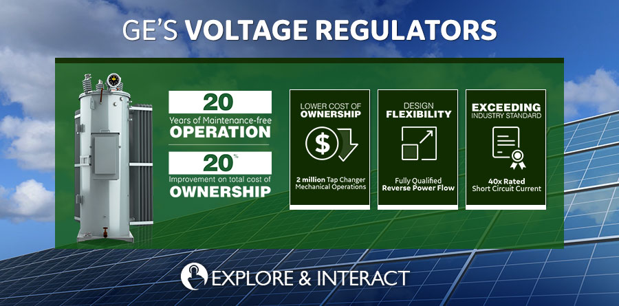

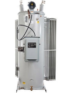
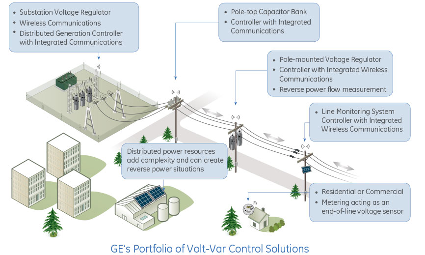
The voltage on modern distribution circuits is becoming increasing difficult to manage. New distributed energy resources, such as solar, combined with the growth of sophisticated loads creates voltage challenges on distribution network systems. GE Vernova's robust and reliable Voltage Regulators help to address these challenges.
GE Vernova's family of voltage regulator products, along with their dedicated controllers, supports both substation and pole-mounted applications as illustrated below.
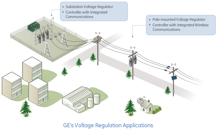
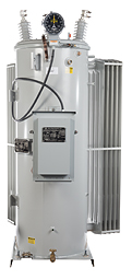
The Pole-mount/platform mount Voltage Regulator (VR-PM) is GE Vernova's premium product for voltage control outside the substation and has established the benchmark in the industry for robust design and operational reliability. It is the only voltage regulator on the market that is guaranteed to support 2 million switch operations and adheres to the latest IEEE C57.15-2009 and C57.131 standards of 40x rated short circuit current.
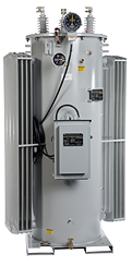
GE Vernova's Substation Voltage Regulator (VR-SS) is a single phase voltage regulator that is intended to support this type of application within a substation. The advantages of single phase units are twofold; they provide the ability to manage each phase independently in the event of unbalanced loads, and they provide redundancy when compared to an individual 3-phase unit.
GE Vernova's Voltage Regulation solutions integrate seamlessly into utility optimization and control strategies for voltage regulation, and is comprised of the following components:
Event: Test ICS File
Date: From Thursday, November 21, 2024 to Friday, November 22, 2024
Time: 9 am to 6 pm
Location: Bangalore, India
If you require more information regarding this event please contact: Udhay
Event: Test ICS File
Date: From Thursday, November 21, 2024 to Friday, November 22, 2024
Time: 9 am to 6 pm
Location: Bangalore, India
If you require more information regarding this event please contact: Udhay