DDFR - Legacy
Distributed Digital Fault Recorder
Data Recording
Key Features
- Retrieves and Archives Transient Fault Records, Sequence of Event Records, and Disturbance Records recorded in protection relays distributed across the substation
- Automatically merges Events recorded in protection relays distributed across the network into a single substation wide Sequence of Event Record
- Stores months of fault and disturbance records internally, facilitating local substation analysis
- Discrete second Ethernet port will allow isolation between the network LAN and the IED’s connected to the DDFR.
Data Recording
The DDFR will detect that new information has been recorded in a relay and automatically retrieve and archive this data. Information that will be archived from protection relays include:
- Transient Fault Records
- Sequence of Event Records
- Disturbance Records
The DDFR is a Transient Fault, Sequence of Event, and Disturbance record archiving system that will seamlessly make available all of the recorded power system information necessary for performing post mortem fault and disturbance analysis.
Sequence of Event Record (SOE)
The DDFR will retrieve the Event Records stored in protection relays distributed across a substation and merge all of these Events into a Station-Wide Sequence of Event Record. Connecting the protection relays to an IRIG-B time clock will synchronize the relay internal clocks with 1 millisecond accuracy and enable the DDFR to create a Station-Wide Event Record that will be an exact representation of the sequence of operations that occurred in the substation.
 Sequence Of Event Records (SOE)
Transient Fault Records
Transient Fault Records (also known as Oscillography records) that are recorded in protection relays will be retrieve by the DDFR and stored in its internal memory space. All Transient Fault Records will be archived using a naming convention that will make it easy for users to relate the Transient Fault records with a particular substation fault. Each record will be stored with a name that includes the exact date and time that the record was initially triggered. If the Transient Fault record was originally recorded in the relay as a COMTRADE file, the DDFR will store this record in its native format; if the protection relay stores it’s record in another format, such as a CSV file, the DDFR will automatically convert this file into the COMTRADE-1999 format so that the record can be analyzed using a standard COMTRADE viewer.
Disturbance Records
Protections relays that are capable of recording Disturbance Records that are used for analyzing extended or evolving power system disturbances such as Voltage Sags or Swells will be retrieved and archived be the DDRF. All Disturbance Records will be archived using a naming convention that will make it easy for users to relate the Disturbance records with a particular power system disturbance. Each record will be stored with a name that includes the exact date and time that the record was initially triggered. Disturbance records will be stored in COMTRADE format and if needed, first convert this file to a COMTRADE file from its native format.
Key Features
- Effortlessly archives recorded data to a permanent enterprise network location or server for remote investigation and analysis
- Non-volatile, solid state storage able to store months worth of fault and disturbance information locally inside the DDFR.
Entreprise Network Archiving
The DDFR Archiving System will automatically copy all data stored in DDFR’s located throughout a companies wide area network into a centralized network location allowing users to analyze fault and disturbance data without having to be at the same location as the DDFR. This DDFR Archiving System that runs on coma network PC or Server can retrieve data from multiple DDFR’s thereby creating a permanent enterprise wide library of all past disturbances on your power system. The information collected by the DDFR Archiving System will be categorized in separate directories for each DDFR, making it easy for users to identify data about faults and disturbances related to each individual substation.
 Archive data collected in DDFR’s distributed across the network into a centralized, accessible network location
Viewing Archived Records
Users can analyze sequence of Event Records, Transient Fault Records, and Disturbance Records that have been stored on a DDFR or archived onto a network location by the DDFR Archiving System by using the EnerVista DDFR Setup Software. The DDFR Setup Software’s Event Record viewer and COMTRADE viewer can access archived records to provide local or remote analysis capability to anyone with access to network storage location.
Sequence of Event Viewer
The EnerVista™ DDFR Setup Software contains a Sequence of Event viewer that allows for easy analysis of the Events stored in the DDFR or archived to the network location. Each recorded event will contain detailed information including:
- Timestamp of Event
- Description of the Event
- Name of Substation
- Name of Source Relay
- Model of the Source Relay
The Sequence of Event viewer provides the ability to sort the recorded events by any of the available fields of information or to perform queries to show only the events that are necessary for troubleshooting a particular fault.
COMTRADE Viewer
The COMTRADE viewer that is included with the EnerVista DDFR Setup Software provides the ability of analyzing the Transient Fault Records and Disturbance Records that have been archived by the DDFR. This full featured COMTRADE viewer allows for analyzing records in a standard time based format that shows the magnitude of all measured quantities, or in Phasor diagram view that shows the magnitude and angle differences between any of the parameters. The COMTRADE viewer can also perform a harmonic analysis on all measured Phasor quantities and display the harmonic content for every point in the record up to the 25th harmonic.
Meet Standards DDFR Requirements
When used with advanced microprocessor based relays such as the UR family, the DDFR System meets or exceeds requirements of International Standards for Digital Fault Recording.
Recommended Products & services

DBF Digital Breaker Failure - Legacy
Manufacturing for this product has been discontinued. As an alternative, please refer to the 8 Series and UR Family relays
DBF Digital Breaker Failure - Legacy
Manufacturing for this product has been discontinued. As an alternative, please refer to the 8 Series and UR Family relays
Recommended Products & services

Feeder Protection
GE Vernova’s distribution feeder protection systems provide advanced protection with...
View MoreDAR Modular Reclosing Relays (Discontinued)
The relays type DAR 2000 are multiple reclose electronic relays, manufactured in modular version, designed to perform automatically the three-phase reclose of a power breaker, tripped by the action of a protection relay.
DAR Modular Reclosing Relays (Discontinued)
The relays type DAR 2000 are multiple reclose electronic relays, manufactured in modular version, designed to perform automatically the three-phase reclose of a power breaker, tripped by the action of a protection relay.
Recommended Products & services
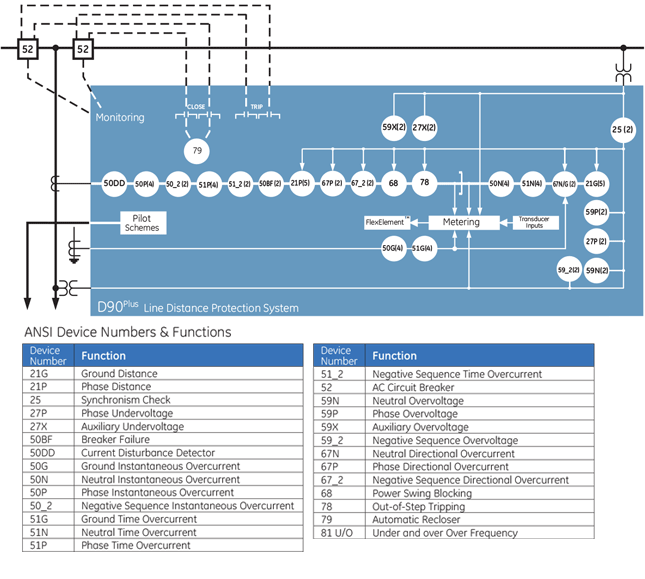
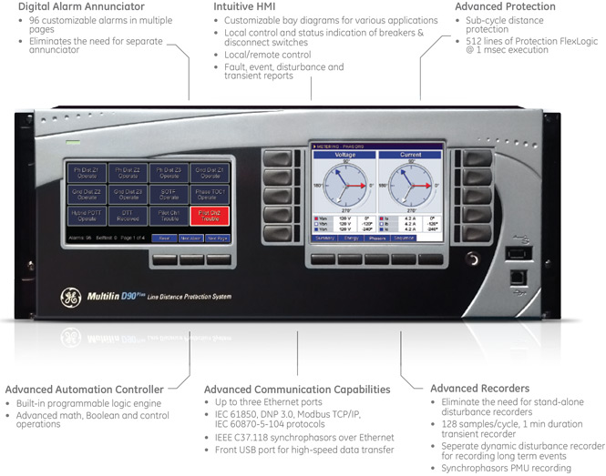
D90Plus – Legacy
Manufacturing for this product has been discontinued. As an alternative, please refer to the D60 with Firmware 7.7 or newer and User Interface Option E: 7” Graphical Front Panel Display.
D90Plus – Legacy
Manufacturing for this product has been discontinued. As an alternative, please refer to the D60 with Firmware 7.7 or newer and User Interface Option E: 7” Graphical Front Panel Display.
Key Features
- Secure time-domain algorithm providing sub-cycle distance protection
- Phase distance with independent compensation settings for in-zone power transformers
- Ground distance with independent self and mutual zero-sequence compensation
- Out-of-step tripping and power swing blocking
- Directional overcurrent: phase, neutral and negative sequence
- Wattmetric zero-sequence directional power
- Under/over frequency
- Synchronism check for dual-breaker applications
- Single/three-pole four-shot dual-breaker autorecloser
- Customization of protection and control functions with independent protection FlexLogic™, FlexCurves™, and FlexElements™
- Advanced automation controller with independent automation programmable logic
- Bay control through front panel HMI
Protection & Control
Modern power systems are under increasing constraints in their ability to transmit power from generation facilities to major load centers, and are forced to operate closer to their natural stability limits. Under these conditions, the critical clearing angle – and corresponding critical clearing time – become progressively smaller and there is an increasing need to minimize the fault clearing time on these constrained circuits.
The D90Plus is ideally suited for application on circuits where fast fault detection and small breaker failure margin are required. The D90Plus allows transmission limits to be maintained or even increased while respecting the transient stability limits of the power system.
Key Features
- Continuous monitoring of AC input channels
- Metering - current, voltage, frequency, power, energy and synchrophasors as per IEEE C37.118
- Transient recorder - 128 samples/cycle, 1 minute or more of storage capacity
- Disturbance recorder – 1 sample/cycle, 5 minutes or more of storage capacity
- Event recorder - 8000 time tagged events, with 0.5 ms scan of digital inputs
- Comprehensive display of metering, phasors, maintenance and fault information via the front panel
Monitoring & Diagnostics
The D90Plus includes detailed metering and recording for all AC signals. Voltage, current, and power metering are built into the relay as a standard feature. Current and voltage parameters are available as total RMS magnitude, and as fundamental frequency magnitude and angle.
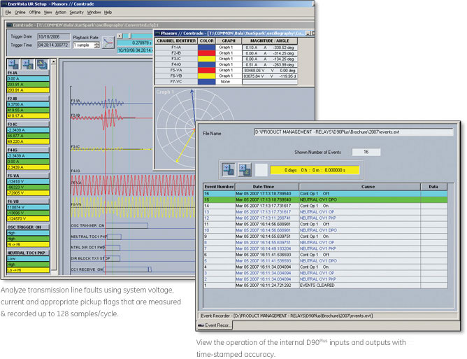
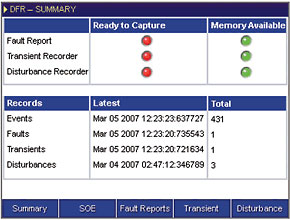 Digital fault recorder summary with the latest information on the events, faults, transients and disturbances.
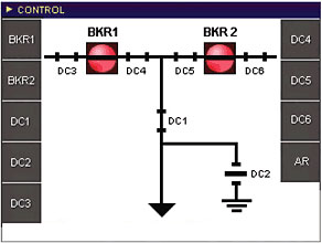 Control screen for the pre-configured bay with breaker & disconnect control in multiple pages using dedicated pushbuttons on the front panel.
Advanced Automation
The D90Plus incorporates advanced automation features including powerful FlexLogic™ (user programmable logic) independent for protection and automation schemes. Combined with the communication capabilities, the D90Plus provides an advanced, highly flexible platform for substation automation applications. The D90Plus integrates seamlessly with other relays for distributed applications like interlocking and special protection schemes.
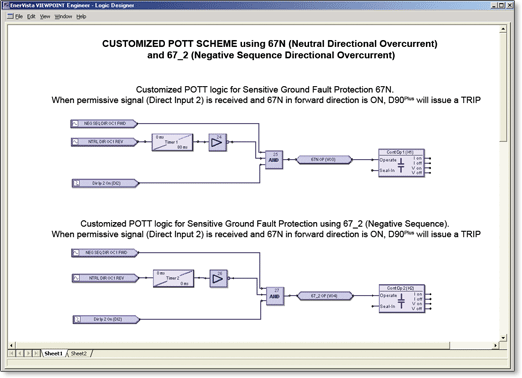 D90Plus user programmable protection logic and independent automation logic allows users to build custom protection and automation schemes.
Key Features
- Multiple protocols - IEC 61850, DNP 3.0 Level 2, Modbus RTU, Modbus TCP/IP, IEC 60870-5-104
- Up to three independent IP addresses
- Increase network availability by reducing failover time to zero through IEC62439-3 "PRP" support
- Front USB port for high-speed communications
Advanced Communications
The D90Plus provides for secure remote data and engineering access, making it easy and flexible to use and integrate into new and existing infrastructures. Fiber optic Ethernet provides high-bandwidth communications allowing for low-latency controls and high-speed file transfers of relay fault and event record information. The availability of three independently configurable Ethernet options provide the means to create fault tolerant communication architectures in an easy, cost-effective manner. The D90Plus supports the most popular industry standard protocols enabling easy, direct integration into SCADA systems.
- IEC 61850
- DNP 3.0
- Ethernet Global Data (EGD)
- IEC 60870-5-104
- Modbus RTU, Modbus TCP/IP
- PRP as per IEC 62439-3
Front Panel
EnerVista™ Software
The EnerVista™ suite is an industry-leading set of software programs that simplifies every aspect of using the D90Plus relay. The EnerVista™ suite provides all the tools to monitor the status of the protected asset, maintain the relay, and integrate information measured by the D90Plus into DCS or SCADA monitoring systems. Convenient COMTRADE and Sequence of Events viewers are an integral part of the UR setup software included with every UR relay, to carry out postmortem event analysis and ensure proper protection system operation. Learn More
Security - Enabling NERC CIP Comliance
Access Control
Multilin devices and relays are designed with simple but powerful security to enable reliability and compliance for virtually any project or implementation. With support for multi-level permissions and multi-factor supervisory controls, Multilin devices can help you manage the integrity of your system during commissioning, testing, implementation, and beyond. The UR and URPlus families provide separate authentication for settings and commands to the system. In addition, as discrete authentications for local and remote access, they also provide a supervisory control factor that can lock or unlock a device for configuration changes and other modifications.
Intrusion Detection
Multilin’s family of protection and control products can also help enable your security perimeter and intrusion detection programs. By providing essential alarming and logging of critical events, Multilin devices can help you detect potential breaches within your system and allow you to respond quickly and effectively. Specifically, unsuccessful access attempts are logged, alarmed, and lead to potential attackers being locked out. This ensures the reliability of your system during questionable activity, and a control factor that can lock or unlock a device for configuration changes and other modifications.

Auditing and Reporting
With the security audit trail reporting feature and support for event logging of key
activities such as configuration changes, Multilin devices can help ensure device and
protection system integrity, and perform forensic auditing of activities and changes
for compliance.

Enhanced Sub-Cycle Distance Protection
- Sub-cycle quadrilateral characteristic added for applications where this characteristic is preferred over the mho characteristic
- True digital CCVT filter to remove voltage transients introduced and provide accurate voltage information for distance protection – requires only three relay settings

Software Ease-of-Use:
EnerVista Viewpoint Engineer now available for graphical configuration of Protection and Automation FlexLogic™

Security Enhancements - Enabling NERC CIP compliance:
- Dual permission access requiring live permission from both the user and from SCADA operators before settings can be changed or commands can be given to the relay
- Remote and local setting and control passwords
- Configurable lockout responses to unsuccessful password access attempts
- Successful password access logged in events record
- Logging of user commands in the security audit trail report creates a record and sequence of events log for troubleshooting and security auditing

New and Enhanced Communications Capabilities
PRP as per IEC62439-3

High-Density I/O Options:
- New high density I/O option modules featuring either 23 optically isolated inputs or 12 Form-A outputs
- Ideal for applications like bay control and monitoring, where a large number of additional I/O are required
Recommended Products & services

Line Protection
GE Vernova's transmission protection solutions deliver the speed and security necessary...
View MoreD485 - Legacy
Modbus to DeviceNet Converter
Sales of this product has been discontinued. Please contact us to discuss alternatives.
D485 - Legacy
Modbus to DeviceNet Converter
Sales of this product has been discontinued. Please contact us to discuss alternatives.
D400-DA - Legacy
Manufacturing for this product has been discontinued. Please contact us to discuss alternatives
The D400-DA is a substation based Fault Detection, Isolation, and Restoration system, designed for improving the reliability of distribution utility networks. With the ability to monitor and control reclosers and switches, the D400-DA can restore unfaulted sections of network thereby improving utility reliability indices and customer satisfaction.
Key Features
- Automatic control and operator assisted reconfiguration modes of operation
- Integrates control into SCADA or DMS systems, or operates as a completely stand alone solution
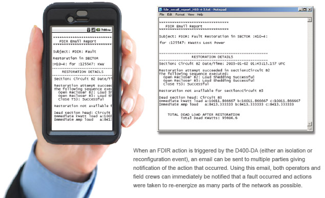
- Email notification to operations and field crew notifying of:
- Fault location
- Reconfiguration actions taken
- KW of customers still without power
- Supports advanced D400-DA Gateway functionality for integrating substation and distribution field equipment
- Equipment Monitored & Controlled
- Breakers and protection relays
- Reclosers and recloser controllers
- Switches and switch controllers
- Fault circuit Indicators
- Communications Protocols
- Protocols to distribution controllers
- Modbus RTU
- Modbus TCP/IP
- DNP 3.0 RTU
- DNP 3.0 TCP/IP
- IEC60870-5-104
- Advanced Gateway Capability
- Data collection, concentration, visibility and media conversion
- Advanced automation utilizing IEC611331 configuration toolsets
- Logging and archiving of device Fault Records & Event Records
- Provides secure access to substation intelligent controllers

Substation Based FDIR/FLISR - Fault Detection, Isolation & Restoration
Reliability Challenges
When faults occur on the distribution network, utility protection and control schemes normally shut down power on the feeder thus disrupting service to many customers. The size of area affected by the outage will directly translate into the number of consumers inconvenienced and some degree of economic loss.
Many distribution utilities are measured as to how well they are serving their customers and may be subjected to regulatory penalties if the regulators feel their performance is not as good as it should be. There are several different measurement indices that are used to gauge utility reliability effectiveness including:
- CML - Measurements indicating number of Customer Minutes Lost per average 100 customers
- CI - Measurements indicating total number Customer Interruptions per average 100 customers
- SAIDI - The System Average Interruption Frequency Index measuring the average number of minutes of interruptions that a customer would experience
- SAIFI - The System Average Interruption Frequency Index measuring the average number of interruptions that a customer would experience
- CAIDI - The Customer Average Interruption Duration Index measures the average outage duration that any given customer would experience
What FDIR Can Provide
Fault Detection, Isolation and Restoration (FDIR) schemes, also known as Fault Location Isolation and Supply Restoration
(FLISR) or Circuit Reconfiguration Schemes, will greatly enhance distribution grid reliability by quickly restoring power to as many customers as possible. By quickly isolating faults and rerouting power from alternate sources to customers on
healthy parts of the network, utilities can greatly reduce the number of customers affected by outages thus reducing their measurement indices and any penalties that may be associated with them.
Methods of Performing FDIR
Centralized Schemes
Utilizes a system wide Distribution Management Systems (DMS) that analyzes the entire network to identify the best way to reconfigure the feeders to restore power after a fault.
Decentralized or Substation Based Schemes
Analyze smaller sections of the network and does not require information about the larger distribution network to reconfigure local sections of the grid that are experiencing outages due to faults.
High Degree of Reliability
Through implementing a D400-DA substation based FDIR scheme, communications needed for monitoring or reconfiguring the network only need to extend from the field recloser and switch controllers to the substation where the D400-DA is located. While communications can be sent back to a Control Center for SCADA management, the complete reconfiguration of the network can be done without a backhaul communications infrastructure. When large scale events occur that can cause multiple utility wide problems, the D400-DA substation based FDIR solution will continue to operate and reconfigure the network even if backhaul communications are lost.
Looped and Multi-Ended Circuits
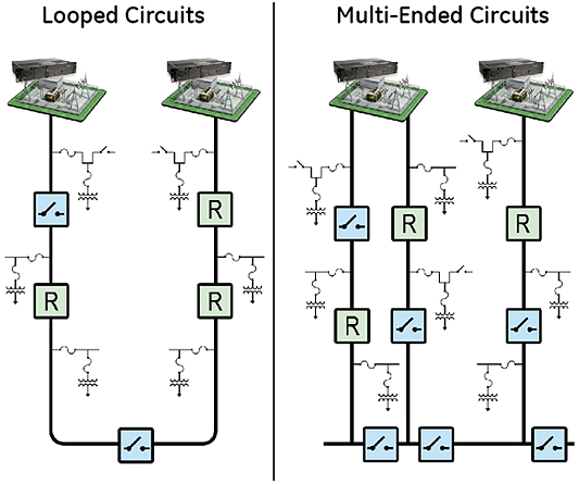
The D400-DA substation based FDIR solution can automate both Looped and Multi-Ended feeder network configurations. The D400-DA can typically restore power to unfaulted sections less than 1 minute after a fault occurs, fast enough to prevent the outage affecting SAIDI and SAIFI indices.
Scalable, Cost-Effective Solution
This D400-DA solution provides a scalable solution for automating from as few as two and as many as twenty circuits or feeders with a single D400-DA. With this scalability, utilities have a cost effective solution that can be incrementally rolled out feeder by feeder or just installed on circuits that are causing the most reliability problems. One D400-DA can automate these twenty circuits whether or not they are emanating from one substation or from multiple substations, as long as the D400-DA can communicate to the controllers in the field.
Feeder Sectors
Each D400-DA can monitor and automate up to twenty feeder sectors. Each sector is defined as a feeder that begins at a breaker and ends at a normally open tie point. The D400-DA that is monitoring a particular sector will be responsible for isolating that sector in the event a fault has occurred on it. This same D400-DA will also be responsible for controlling the tie switches to other sectors in the event that more load will be added to it to restore adjoining dead sectors.
Devices Controlled
Each D400-DA can communicate with and control up to 100 devices found within the sectors it is monitoring. Devices interfaced with it may include protection relays, recloser controllers, switch controllers and fault circuit indicators.
Modes of Operation
The D400-DA has two main modes of operation for isolating and reconfiguring distribution networks: Automatic Reconfiguration and Operator Assisted Reconfiguration.
Automatic Reconfiguration
– In Automatic Reconfiguration mode, the D400-DA will identify outages on its monitored sectors and take action to restore power to the maximum number of customers as possible. It performs the actions without any interaction required from system operators.
Operator Assisted Reconfiguration
– In Operator Assisted Reconfiguration mode, the D400-DA will require confirmation that system operators agree with the recommended action before these actions are carried out. This mode of operation is often used by utilities for an initial trial period of time to have their operators get comfortable with the D400-DA recommendation before going into full Automatic Reconfiguration mode.
Reconfiguration Triggers
While the D400-DA is monitoring its feeders, there are several sequences that will initiate a reconfiguration action:
- Protection Lockout: The operation of a protection function on a protection relay or recloser controller
- Loss of Voltage: The voltage on a sector has dropped below the programmed voltage threshold for an extended period of time defined by the utility
- Loss of Voltage After Fault: An intermediate loss of voltage after a downstream overcurrent detection
Network Topology Modeling and Sector Definition
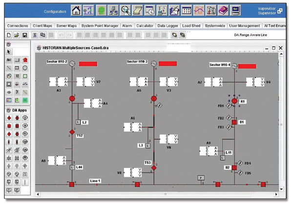
The D400-DA system configuration software is an easy-to-use online tool that allows for system modeling and FDIR sector configuration. When being used in Operator Assisted Mode, this tool can be the operator interface for acknowledging or rejecting reconfiguration scenarios proposed by the D400-DA FDIR system.
Isolation
When a reconfiguration action has been triggered, the first course of action the D400-DA will take is to isolate any faulted sections on the line. Isolation actions will attempt to minimize the number of customers falling within an isolated section. When the D400-DA is in Operator Assisted Mode, it will give a recommendation to the operators on the best course of action to take to isolate the fault. If the operator does not agree with the recommended action, the D400-DA will calculate the next optimal scenario and propose that to the operators.
Isolation on Sectors with Distributed Generation
When a fault occurs on a sector of the line, the D400-DA will open all of the available switches to completely isolate the fault. On radial feeders or laterals, if additional switches are located downstream of the fault, the D400-DA will also open those switches to prevent any other sources such as distributed generation that may back-feed the fault.
Restoration
Once the D400-DA has ensured any faults are isolated, it will attempt reconfigure the network to restore power to as many customers as possible. When operating in Operator Assisted Mode, the D400-DA will first ask for confirmation from the operator before taking any action. If the operator does not agree with the recommended action, the D400-DA will calculate the next optimal scenario and propose that to the operator.
Historical Load Modeling
To ensure that the source being used to re-energize a sector of the feeder can support the additional load, the D400-DA calculates the short term power requirements based on a 15 minute sliding peak demand window with 1 minute resolution. The D400-DA also identifies the long term load requirements using a 30 days sliding window with a 1 day resolution and a 15 minute averaging period.
Dead Line Verification
Before reconfiguring the network, the D400-DA will verify that the voltage on the dead sector has dropped below configurable thresholds to ensure that the line is still not energized due to any residual distributed generation sources.
Alternate Protection Groups
Before reenergizing a line, the D400-DA will alter the setting groups on any recloser or switch controllers on the line so that the protection functions will be coordinated for the new loads and direction of power flow.
E-mail Notification

Advanced Gateway
The D400-DA collects data from substation protection, control, monitoring, RTU, and intelligent devices, pre-processes the data and moves it up to EMS and DMS SCADA systems providing centralized substation management.
Advanced Automation
The D400-DA provides the computing platform necessary to automate substation procedures, such that intricate processes are carried out safely and efficiently by creating custom automation programs using IEC 61131 compliant tools, and perform basic math functions on data points using the built-in Calculator tool.
Fault Recording/Data Logging
Using pass-through connections, users can extract valuable non-operational data such as digital fault recording (DFR) records and event files. The user can also access the historical log files and upload the archived data for trending and analysis.
Secure Remote Access
The D400-DA allows maintenance and relay engineers to securely access substation devices, locally or remotely, through advanced visualizations and communication tools, increasing productivity.
Hardware
The D400-DA is built on a flexible, high performance, expandable disk-less and fan-less platform that is powered by a 1.0Ghz processor.
Two Ethernet networks are supported with separate multiport switches. An IRIG-B format time protocol input/distribution module is also supported. Isolated serial port media is selected for each pair of ports.

Redundant Power Supplies
The D400-DA has dual redundant, hot swappable power supplies, ensuring continuous uptime. Each power supply can be connected to a different source. As an example Power supply 1 can be connected to Mains, while power supply 2 is connected to the battery system. Power Supply Health Monitoring raises a SCADA point alarm when either power supply fails. This allows an alarm to be transmitted to the EMS /OMS or DMS system, where a field personnel can be dispatched to replace the failed supply, all without service disruption.
Time Sync Support
The D400-DA has extensive support for various time sync methodologies and will accept time sync signals from SNTP/NTP Servers, IRIG-B (un-modulated/modulated), and SCADA protocols. The D400-DA can also distribute this time sync information through its built-in IRIG-B distribution interface, SCADA protocols, and/or through the RS232 ports directly.
Recommended Products & services
Substation Systems
Electric utilities and independent power producers are under increasing pressure to...
View More
Integrated Substation Control System
Next generation substation control and automation Network operators/owners are seeing...
View More
DS Agile Substation Gateway
GE Vernova’s DS Agile Substation Gateway substation gateways perform the...
View MoreMultilin D.20 RIO – Legacy
Distributed I/O Controller
Manufacturing for D.20 RIO has been discontinued. As an alternative, please refer to the G100 or G500.
Multilin D.20 RIO – Legacy
Distributed I/O Controller
Manufacturing for D.20 RIO has been discontinued. As an alternative, please refer to the G100 or G500.
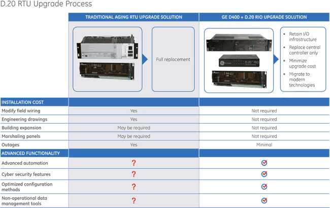
Cost Effective Upgrade Solution
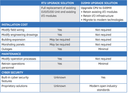
Utilities have large investments in hard wired automation systems. As a piece of equipment ages it fails more frequently, takes longer to repair, and eventually reaches the end of its life. Re-design and forklift replacements require utilities to re-engineer substation designs, replace field wiring, and re-train staff to manage and maintain the system, which is a costly endeavor.
The D.20 RIO option with support for D.20 communications provides a cost effective alternative to upgrades of legacy D20 RTUs. Simply replace the failed or end of life D20 unit with a D400 Gateway and D.20 RIO module, plug the D.20 interface cable into the D.20 RIO, connect the D.20 RIO to the D400 or an Ethernet port in the substation LAN and you are ready to add modern functionality to the D400 series of Substation Gateways including:
- Cyber security features for integration into NERC CIP environments
- Secure real time browser access
- Browser-based HMI interface
- Secure remote engineering access
- IEC 61850 capabilities
- Automatic record retrieval (fault records, SOE, settings files, any other file available in the IED)
I/O Where You Need It, Minimizing Wiring Cost
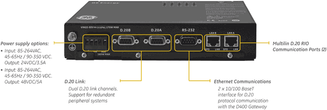
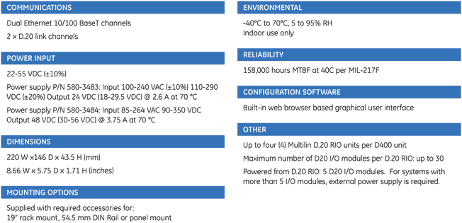
The D.20 RIO Distributed I/O Controller is a small form factor stand-alone device that supports two D.20 link channels for communication with the D20 series of input / output modules.
- Interface with standard D20 I/O (status, analog input, control and combination input) peripheral modules
- Support for up to 30 I/O modules in a single D.20 RIO, or distributed over up to four D.20 RIO devices within the substation
- Small form factor with multiple mounting options for installation flexibility: 19" Rack, panel mount or DIN Rail
Use the D.20 RIO module to install input / output modules in the substation LAN. No substation LAN? No problem, connect the optional D.20 RIO device directly to the built-in D400 Ethernet switch.

User Interface
Front Panel
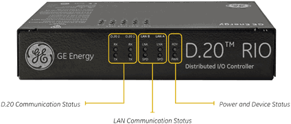
Back Panel
Techanical Specifications
Recommended Products & services

Gateways and RTUs
GE Vernova offers an industry-leading suite of multifunction servers, gateways, RTUs, and...
View MoreMultilin D20MX Substation Controller Legacy
Simple to Advanced Substation Automation Control
Manufacturing for the D20MX portfolio has been discontinued. Please contact GE Vernova for availability.
Multilin D20MX Substation Controller Legacy
Simple to Advanced Substation Automation Control
Manufacturing for the D20MX portfolio has been discontinued. Please contact GE Vernova for availability.
Advanced Controller
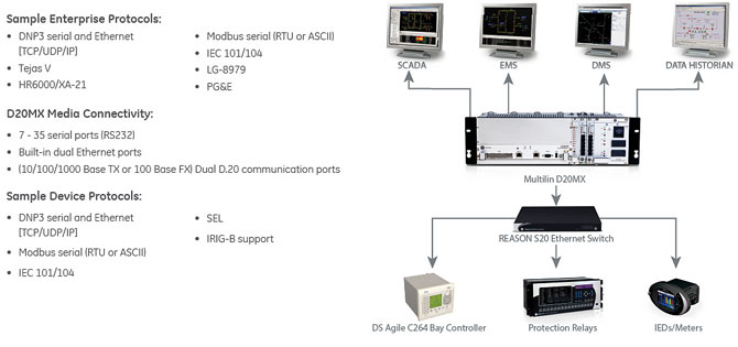
The Multilin D20MX Substation Controller collects, filters, and sorts data from a wide range of intelligent devices (RTUs, relays, meters) in the substation. The D20MX preserves original data time stamps for accurate sequence of event (SOE) logs, allowing data from large diverse geographic regions and time zones to be analyzed in extreme detail. Data can be presented simultaneously to multiple SCADA hosts. The D20MX comes with a built-in suite of protocols and security applications to facilitate integration with various substation devices and SCADA hosts.
D20MX is the sixth generation of D20 CPUs designed to provide a smooth migration path for D20 users to extend the life of aging D20 systems. It introduces a new and modern network security feature suite that enables effective compliance with NERC-CIP requirements, using open and trusted standards and protocols that allow integration with modern cyber security systems and tools.
Advanced Substation Controller Connectivity
D20MX Upgrade Process
The Multilin D20MX provides a cost-effective alternative to upgrades of legacy D20/D200 RTUs. This means that the investments made in GE Vernova’s automation systems keep paying dividends beyond their originally projected end of life. Simply replace the Multilin D20/D200 processor module with a Multilin D20MX and migrate the device configuration to extend the life of the existing D20/D200 Controller. Add cyber security features for integration into NERC-CIP environments. As technology changes with market demands, GE Vernova continues to invest in a partnership with their customers through advanced modular design principals
Integration into NERC-CIP Environments
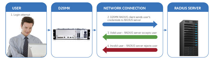
The Multilin D20MX supports a comprehensive set of security functions to allow a seamless integration with existing IT department policies. Built-in cyber security features, such as Remote Authentication Dial-In User Service (RADIUS), Role Based Access Control (RBAC), and user activity logging, provide a complete security toolkit required to enable simpler and more efficient compliance with NERC-CIP requirements, using open and trusted standards and protocols, that allow integration with modern cyber security systems and tools.
Centralized Authentication and Authorization
Hardware Overview
Backwards Compatibility with Earlier Vintages of Multilin D20 RTUs
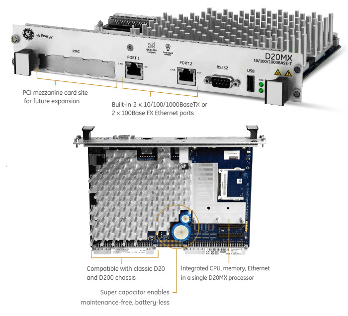
The Multilin D20MX is an embedded single board computer powered by a 667 MHz PowerQUICC II Pro processor pin-for-pin compatible unit with existing D20 Processors and accessories, such as chassis, D20 remote I/O peripherals, modems.
Fully Equipped Out-of-the-Box
Previous generations of D20/D200 RTUs required add-on system components and software to support Ethernet communications and optional memory expansion. The new D20MX is equipped by default with integrated memory, 10/100/1000BASE-TX or 100BASE-FX IEEE 802.3 compliant communications and a core load firmware with a comprehensive set of key substation automation applications.
D20 I/O options
A complete family of substation hardened I/O modules makes the D20MX controller scalable to both large and small substations. A distributed architecture with both ring and star topologies allows for easy expandability and remote placement of I/O modules. The following I/O modules are available in a variety of models with I/O ranges up to 300VDC.
| D20S - 64 channel status input module | Buy Now |
| D20A - 32 channel DC Analog input module | Buy Now |
| D20K - 32 channel control output module | Buy Now |
| D20KI - 8 external interposer relay pairs module | Buy Now |
| D20C - 16 status input, 8 control output, optional 16 DC analog inputs or 8 analog inputs and 8 analog outputs | Buy Now |
I/O with DNP Communication
The DNP I/O modules are data collection and control devices that combine the DNP 3.0 communications protocol with our existing industry proven and robust line of I/O modules. The DNP I/O modules implement the industry standard DNP 3.0 (Level 2) slave protocol over a single RS485 interface to provide expandable I/O functionality for the D400, D25 and iBox product lines, as well as third-party products.
The following DNP I/O modules are available:
Recommended Products & services
Gateways and RTUs
GE Vernova offers an industry-leading suite of multifunction servers, gateways, RTUs, and...
View MoreCHC Instantaneous Overcurrent - Legacy
Manufacturing for CHC has been discontinued. As an alternative, please refer to P153, P14N or
CHC Instantaneous Overcurrent - Legacy
Manufacturing for CHC has been discontinued. As an alternative, please refer to P153, P14N or
Recommended Products & services
CFVB Voltage-balance Relay - Legacy
Manufacturing for CFVB has been discontinued.
CFVB Voltage-balance Relay - Legacy
Manufacturing for CFVB has been discontinued.