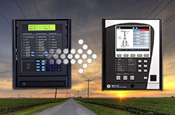
Legacy MU Agile AMU
Analogue Merging Unit
Manufacturing for this product was discontinued as of December 31, 2014. As an alternative, please consider MU320E.
Digitise the output of conventional instrument transformers in the substation with this compact, accurate and withdrawable device. The AMU complements the MiCOM Px40 range of relays with an IEC 61850-9-2LE interface for building digital bays or full digital substations.
Recommended Products & services
Merging Units
Merging units are a key element of the process bus concept, enabling the digitization of...
View MoreALPS Advanced Line Protection System - Legacy
Recommended Products & services

Line Protection
GE Vernova's transmission protection solutions deliver the speed and security necessary...
View MoreMultilin A60 - Legacy
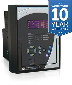
Manufacturing for this product has been discontinued. As an alternative, please refer to the 350 or 8 Series relays.
Multilin A60 - Legacy
Manufacturing for this product has been discontinued. As an alternative, please refer to the 350 or 8 Series relays.
- Independent device provides continuous, always on, operation to maximize equipment protection
- Continuous health monitoring of optical sensors, fiber cables, and control unit to ensure reliable operation
- Direct connection to breaker trip circuit using solid state output relays, for increased operating speed
- Reliable and deterministic multi-stage (light and pressure) detection with optional supervisory input reduces nuisance tripping
- Simplified installation and configuration with sensor auto-calibration and no requirement for additional setup software
- Scalable arc flash system, allowing for multiple unit connectivity for large installations
- No requirement to install additional CT's reducing time and costs associated with installation and commissioning
- Suitable for both new and retrofit applications
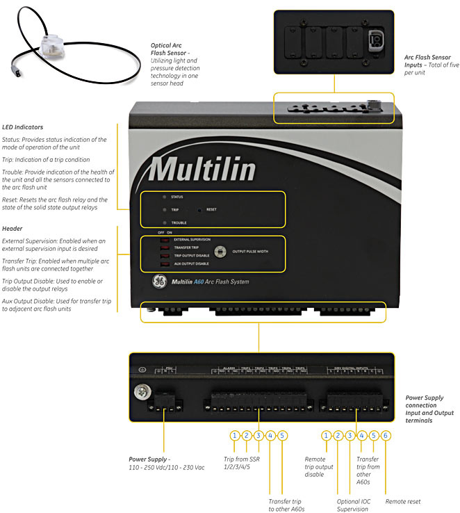
An arc flash event is the sudden release of electrical energy through the air. The resulting forces can produce temperatures up to 35,000°F, in less than one thousandths of a second, causing copper to turn into plasma expanding by 67,000 times. With these type of extreme events, fast, reliable arc flash detection is critical to avoid significant damage to equipment and reduce the repair and replacement costs, as well as downtime of the power system. The Multilin A60 Arc Flash System utilizes a unique sensing method that detects both light and pressurized sound signals that occur during an arc flash event, enabling more reliable and faster operating times to reduce the total arc energy generated. Utilizing a patented arc flash sensing method, the Multilin A60 is able to reliably detect an arc flash event in as fast as 1 msec.
Light and pressure wave arc flash detection
Based on a known time relationship between the speed of light and sound (pressure wave), GE Vernova's patented sensor is able to detect and issue a trigger signal to clear the fault in under 2 milliseconds – significantly reducing incident energy from an arc flash event. Specifically, the sensor head detects these two key factors (light and pressure wave) using LEDs, bare fiber and a membrane.
During an arc flash event, the diaphragm vibrates due to the pressurized sound wave creating a signature which is recognized by the Multilin A60. It is this unique combination of light and pressure wave detection that ensures reliable and fast detection of an arc flash event.
The Multilin A60 supports up to five sensors per unit providing optimal coverage in a typical two-high medium voltage switchgear section. To cover a larger area or for multi-section applications, Multilin A60's may be daisy chained together.
Well suited for both new and existing applications
As a stand-alone unit, the Multilin A60 relay is DIN rail mountable and should be mounted inside the control cabinet of the medium voltage switchgear or motor control center. Sensors should be installed where there is a high probability of an arc flash occurring.
As the Multilin A60 utilizes both light and pressure to detect an arc flash condition, installation and wiring of external CT's are not required. An external current supervision from a separate Instantaneous Over Current (IOC) device may be used and connected as a contact input for enhanced security and mitigation of nuisance tripping.
Calibrating & testing
The Multilin A60 provides an auto-calibration function for the sensors reducing total commissioning and testing time. Once installed and powered, the device will first run in calibration mode. This mode, sets the thresholds for both the light and pressurized sound based on surrounding or ambient conditions. As surrounding conditions may change, the Multilin A60 may be re-calibrated at anytime.
Control panel interface
Typical wiring diagrams & application examples
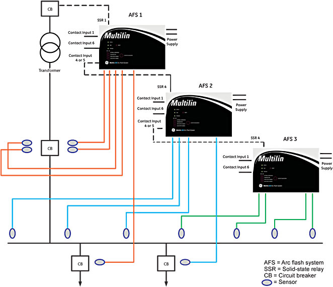
This figure shows the typical wiring diagram of the Multilin A60 Arc Flash System. The typical wiring diagram shows the connection of the input and output relays and the connected sources. The wiring diagram also shows the connection of the supervisory circuit (option) to the A60 unit.
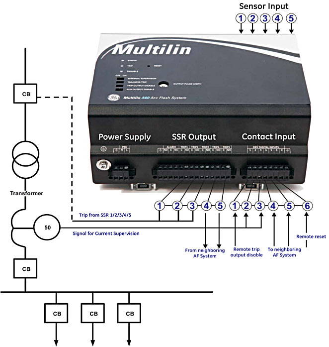
This application example below describes the ability of the Multilin A60 to be deployed in a cascading configuration across multiple MV switchgear sections and compartments, including through a substation bus bar vault. The Multilin A60 sensors should be installed at a certain distance from each other to ensure coverage of the entire bus bar.
By connecting devices together using the transfer trip input/output, individual Multilin A60 devices may receive a transfer trip signal from an upstream or downstream device, ensuring fast, reliable detection of an arc flash event in large MV switchgear applications.
Recommended Products & services

Feeder Protection
GE Vernova’s distribution feeder protection systems provide advanced protection with...
View MoreMultilin 850R - Legacy
Recloser & Switch Controller
Manufacturing for the 850R has been discontinued. As an alternative, please refer to the R650.
Multilin 850R - Legacy
Recloser & Switch Controller
Manufacturing for the 850R has been discontinued. As an alternative, please refer to the R650.
Recloser Overview
The role of a recloser in a distribution network has developed in line with the increasing need for operators to minimize outage duration and the numbers of customers affected by faults, which in turn helps maximize performance according to reliability indices like CAIDI/SAIDI. As a result, it has two main functions. Its primary function is to clear the fault when it occurs as quickly as possible. Secondly, if the fault is permanent, the recloser takes on a sectionalising role driven by logic or commands. These control systems are dependent on the data delivered by the recloser on three levels: general monitoring from a historic perspective, fault data at the time of fault and pre/post fault data.
850R Primary Function
Multifunction Distribution Automation Controller with Recloser/Switch/Sectionalizer (Tie-Bus) control for overhead applications
- Improved distribution network reliability with a fast and reliable dynamic tripping and 4 consecutive shot 1-Phase or 3-Phase Autoreclosing
- Supports 6 Low Energy Analog (LEA) or 4 traditional voltage Input
- Autoreclosing integrated high speed driving electronics board with capacitor and battery charging capabilitie
- 5 shot switch control function included within the control
- 6 setting groups gives flexibility in building FDIR/ FLISR logic as well as loop schemes for 1/3 pole operations, improving system reliability
- Adaptive reclose with zone/sequence coordination
- Support for 41 recloser curves
- Flexibility to assign the current and voltage terminal configuration to match the primary recloser and user terminal configuration
- Integrated Distribute Energy Resources (DER) management including local islanding features to achieve IEEE 1547-2018
- Comprehensive power quality monitoring as per IEEE 519
- Real time asset monitoring for increased reliability and optimized asset life
- Remote device management and easy maintenance with secure WiFi connectivity
850R for Distribution Automation
From simple automation to advanced analytics, the 850R provides the flexibility and scalability required to meet unique application requirements for the distribution utilities.
Distributed FDIR
The decision making algorithm utilized in Distributed FDIR is spread among the field devices in the covered area using IEC 61850 GOOSE multicast. This approach eliminates the need for a centralized or decentralized system, and therefore reduces the total cost. Since this approach uses IEC 61850 GOOSE peer-to-peer communication messages among the field devices, it can be much faster and cost effective than other options.
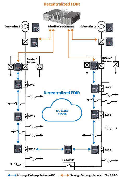
Decentralized FDIR
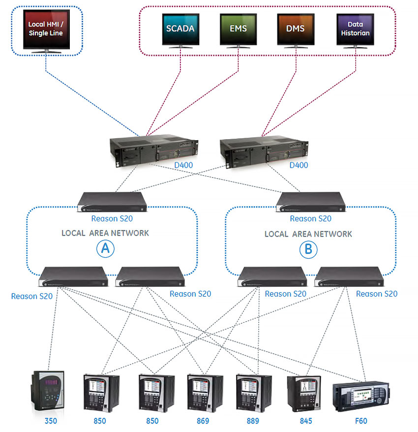
Decentralized FDIR is a model-based scheme with the decision making algorithm residing at the substation level rather than the DMS level. The substation controllers, known as Distribution Automation Controllers (DACs), can also send the received data to the DMS level for supervisory monitoring and control in a more efficient manner. Automation applications, such as IVVC, can still be added at the substation level. The 850R supports redundant Ethernet and fiber port physical interface options and a wide range of industry standard protocols for communication, namely Modbus TCP/IP, DNP 3.0, IEC 60870-5-101, IEC 60870-5-103, IEC 60870-5-104, IEC 61850 ED2, IEC 62439 / PRP.
Protection & Control
The 850R provides secure and reliable protection & autoreclose functionality by offering a comprehensive range of standard and advanced protection and control elements. The controller provides directional and non-directional overcurrent protection along with the option of single-phase tripping and reclosing. Additionally, voltage and frequency protection elements may be used to disconnect Distributed Energy Resources (DER).
Multilin 850R feeder protection relay functional block diagram
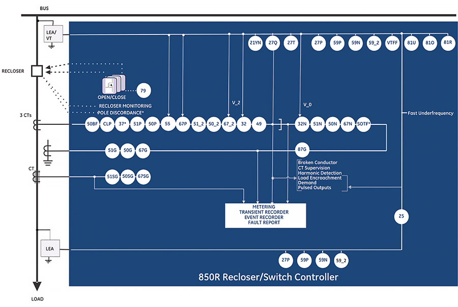
ANSI Device Numbers & Functions
| Device Number | Function |
|---|---|
| 21YN | YN Neutral Admittance |
| 25 | Synchrocheck |
| 27P | Phase Undervoltage |
| 27Q | UV Reactive Power |
| 27T | Timed Undervoltage Protection |
| 27X | Auxiliary Undervoltage |
| 32 | Directional Power |
| 32N | Wattmetric Ground Fault (Wattmetric zero sequence directional) |
| 37 | Undercurrent |
| 49 | Thermal Overload |
| 50BF | Breaker Failure |
| 50G | Ground Instantaneous Overcurrent |
| 50SG | Sensitive Ground Instantaneous Overcurrent |
| 50N | Neutral Instantaneous Overcurrent |
| 50P | Phase Instantaneous Overcurrent |
| 50_2 | Negative Sequence Instantaneous Overcurrent |
| 51G | Ground Time Overcurrent |
| Device Number | Function |
|---|---|
| 51SG | Sensitive Ground Time Overcurrent |
| 51N | Neutral Time Overcurrent |
| 51P | Phase Time Overcurrent |
| 51_2 | Negative Sequence Time Overcurrent |
| 59N | Neutral Overvoltage |
| 59P | Phase Overvoltage |
| 59X | Auxiliary Overvoltage |
| 59_2 | Negative Sequence Overvoltage |
| 67G | Ground Directional Element |
| 67SG | Sensitive Ground Directional Element |
| 67N | Neutral Directional Element |
| 67P | Phase Directional Element |
| 67_2 | Negative Sequence Directional Element |
| 79 | Automatic Recloser |
| 81O | Overfrequency |
| 81U | Underfrequency |
| Device Number | Function |
|---|---|
| 81R | Frequency Rate of Change |
| 87G | Restricted Ground Fault (RGF) |
| CLP | Cold Load Pickup |
| I1/12 | Broken Conductor |
| MCB | Manual Close Blocking |
| SOTF | Switch Onto Fault |
| TGFD | Transient Ground Fault Detection |
| VTFF | Voltage Transformer Fuse Failure |
| Auto Sectionalizer | |
| Battery Testing and Monitoring | |
| Capacitor and Coil Monitoring | |
| Fast Underfrequency | |
| Load Encroachment | |
| Overhead Switch Health Monitoring | |
| Power Loss | |
| PseudoVoltage | |
| Recloser Coil, Cap Voltage, and Health Monitoring | |
| Supply Switchover Function |
Distribution Automation
From simple automation to advanced analytics, the 850R provides the flexibility and scalability required to meet unique application requirements for the distribution utilities.
Distributed FDIR
The decision making algorithm utilized in Distributed FDIR is spread among the field devices in the covered area using IEC 61850 GOOSE multicast. This approach eliminates the need for a centralized or decentralized system, and therefore reduces the total cost. Since this approach uses IEC 61850 GOOSE peer-to-peer communication messages among the field devices, it can be much faster and cost effective than other options.
Decentralized FDIR
Decentralized FDIR is a model-based scheme with the decision making algorithm residing at the substation level rather than the DMS level. The substation controllers, known as Distribution Automation Controllers (DACs), can also send the received data to the DMS level for supervisory monitoring and control in a more efficient manner. Automation applications, such as IVVC, can still be added at the substation level.
Communications
The 850 provides advanced communications technologies for remote data and engineering access, making it easy and flexible to use and integrate into new and existing infrastructures. Direct support for fiber optic Ethernet provide s high-bandwidth communications, allowing for low-latency controls and high-speed file transfers of relay fault and event record information. The 850 also supports two independent IP addresses, providing high flexibility for the most challenging of communication networks.
Providing several Ethernet and serial port options, dual independent Ethernet Ports, and support for a wide range of industry standard protocols, the 850 enables easy, direct integration into DCS and SCADA systems. The 850 supports the following protocols:
- IEC 61850 Ed2, IEC 62439 / PRP
- DNP 3.0, IEC 60870-5-103, IEC 60870-5-104
- Modbus RTU, Modbus TCP/IP
The 850 has two interfaces as USB front port and Wi-Fi for ease of access to the relay. Wi-Fi Connectivity:
- Simplify set-up and configuration
- Simplify diagnostic retrieval
- Eliminate personnel in front of switchgear
- WPA-2 security
Cyber Security
The 850 cyber security enables the device to deliver full cyber security features that help operators to comply with NERC CIP guidelines and regulations.
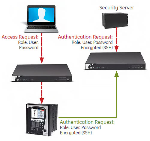
AAA Server Support (Radius/LDAP)
Enables integration with centrally managed authentication and accounting of all user activities and uses modern industry best practices and standards that meet and exceed NERC CIP requirements for authentication and password management.
Role Based Access Control (RBAC)
Efficiently administrate users and roles within UR devices. The new and advanced access functions allow users to configure up to five roles for up to eight configurable users with independent passwords. The standard “Remote Authentication Dial In User Service” (Radius) is used for authentication.
Event Recorder (Syslog for SEM)
Capture all cyber security related events within a SOE element (login, logout, invalid password attempts, remote/local access, user in session, settings change, FW update, etc), and then serve and classify data by security level using standard Syslog data format. This will enable integration with established SEM (Security Event Management) systems.
Advanced Monitoring and Diagnostics
Coil Circuit Supervision
The driving electronics board checks the coil connection continuity of the trip/close circuit, as well as the leakage current to ground. When magnitude of any phase current falls below the undercurrent trip pickup level for the time specified by the undercurrent trip delay. The alarm and trip pickup levels should be set lower than the lowest feeder loading during normal operations.
Capacitor Voltage Alarm
The Capacitor Voltage Alarm function defines the low voltage alarm for the internal/external capacitor charging power supply circuit. This rated voltage is used for charging the external capacitors that open and close the single-pole of the recloser. If the measured voltage of the capacitors is less than the configured percentage of the rated voltage, then the Cap Volt OP operand is generated. In addition, to prevent the charger from damage due to overloading or load short faults created by incorrect wiring, bad capacitors, or hardware failures, the 850R automatically turns off the capacitor charger to prevent damage.
Recloser Wear and Recloser/OHSW Health Monitoring
The 850R relay provides recloser/OHSW health information by monitoring and analyzing the operation count, arcing energy of breaking current, arcing time, opening time, and closing time when applicable. The recloser health status depends on many factors, such as permissible operation number, magnitude of breaking current, mechanical wear and contact wear.
Time of Day Timer
The Time of Day Timer function provides the user with the ability to program control actions based on real time. There are two identical Time of Day Timers.
Application
Monitoring of the total accumulated energy/accumulated demand/minimum and maximum power demand at the end of an event or a shift interval. A shift can be defined by the breaker status operand (opclosed) or operand derived from the Time of Day Timer element.
Voltage Disturbance
The Voltage disturbance function of Voltage Swell and Voltage Sag, as described in IEEE 1159-2009. When the voltage on any phase drops below this level a voltage sag condition occurs. Voltage sags are usually associated with system faults but can also be caused by switching heavy loads or starting large motors. Short duration voltage sag may cause process disruptions. Voltage swells are usually associated with system fault conditions, but they are much less common than voltage sags. An SLG fault on the system can cause a swell to occur, resulting in a temporary voltage rise on the healthy phases. Swells can also be caused by switching off a large load, load shedding, or switching on a large capacitor bank. Voltage swell may cause failure of the components depending upon the magnitude and frequency of occurrence.
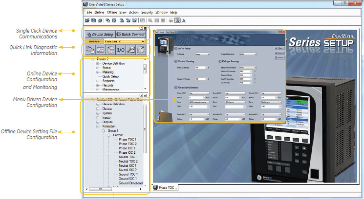
Software and Configuration
The EnerVista™ suite is an industry-leading set of software programs that simplifies every aspect of using the Multilin 8 Series. EnerVista provides all the tools to monitor the status of the protected asset, maintain the device and integrate the information measured by the Multilin 8 Series, into SCADA or DCS process control systems. The ability to easily view sequence of events is an integral part of the setup software, as postmortem event analysis is critical to proper system management.
EnerVista Launchpad
EnerVista Launchpad is a powerful software package that provides users with all the setup and support tools needed for configuring and maintaining Multilin products. The setup tools within Launchpad allow for the configuration of devices in real-time, by communicating via serial, Ethernet or modem connections, or offline by creating device setting files to be sent to devices at a later time. Included in Launchpad is a document archiving and management system that ensures critical documentation is up-to-date and available when needed.
8 Series Setup Software
8 Series Setup Software is a single setup and configuration across the platform and can reduce device setup and configuration time.
Recommended Products & services
Controllers
GE Vernova offers an industry-leading suite of controllers that support a variety of...
View MoreMultilin 8 Series
Innovative protection and control relay platform
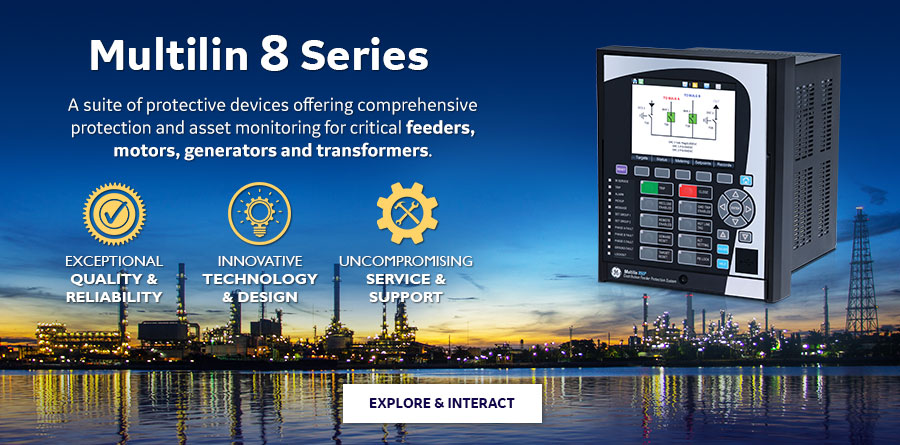
The Multilin™ 8 Series platform of advanced protection and control relays delivers high quality and performance management, protection and control for transformer, generator, motor and feeder applications.
Comprised of the 845 transformer protection relays, 889 generator protection relays, 869 motor protection relays and 850 feeder protection relays, the 8 Series platform features innovative technology and design, as well as uncompromising service and support.
Multilin 8 Series
Innovative protection and control relay platform
The Multilin™ 8 Series platform of advanced protection and control relays delivers high quality and performance management, protection and control for transformer, generator, motor and feeder applications.
Comprised of the 845 transformer protection relays, 889 generator protection relays, 869 motor protection relays and 850 feeder protection relays, the 8 Series platform features innovative technology and design, as well as uncompromising service and support.
Platform Overview
The Multilin 8 Series platform delivers the highest level of quality, reliability and performance with…
Innovative Technology & Design
- Patented environmental monitoring and diagnostics helps visibility on change in environmental parameters
- Advanced, flexible and embedded communications: IEC® 61850 Ed2, IEC 62439/PRP, Modbus® RTU & TCP/IP, DNP3.0, IEC 60870-5-104, IEC 60870-5-103
- Single setup and configuration across the platform
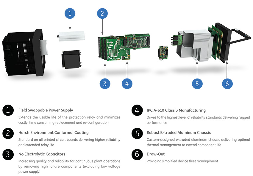
- Field swappable power supply
- Draw-out design simplifies testing, commissioning and maintenance, thereby increasing process uptime
- Optional Wi-Fi connectivity minimizes system configuration and provides safe relay programming and diagnostic retrieval
- Elimination of electrolytic capacitors
Exceptional Quality & Reliability
- IPC A-610-E Class 3 Manufacturing standards – highest industry standards for electronic manufacturing
- Highest reliability standards for electronics testing
- Environmental Stress Screening and full functional testing
- Rated for IP54 applications
- Standard Harsh Conformal Coating
Uncompromising Service & Support
- Covered under GE Vernova’s 10 year warranty plan
- Fully designed, tested and assembled at GE Vernova facilities
Monitoring & Diagnostics
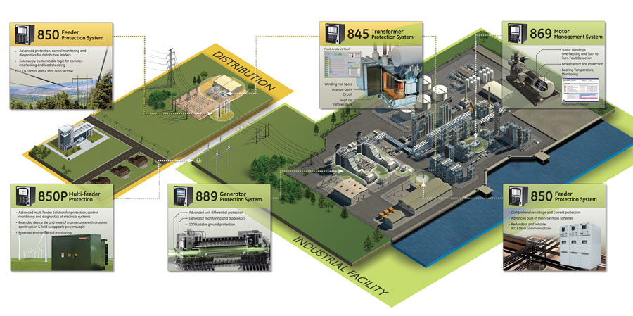
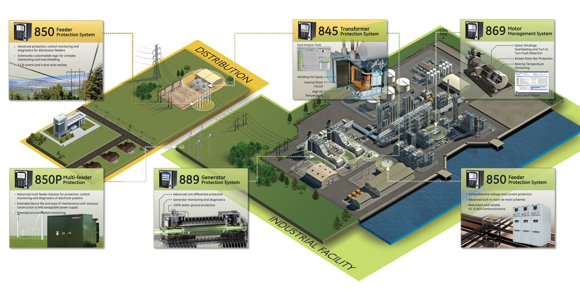
The Multilin 8 Series platform features a number of robust capabilities for motor, transformer, generator and feeder monitoring and diagnostics.
Motor Monitoring & Diagnostics
Integrated, cost effective motor monitoring and diagnostics are available in the Multilin 869 motor protection relay. Existing relay data is leveraged to detect electrical, thermal or mechanical abnormalities before they become critical motor failures. Motor monitoring and diagnostic capabilities include:
- Advanced monitoring and trending for condition-based status of electrical conditions that can affect motor performance
- Continuous, proactive monitoring of thermal capacity used for early identification of thermal stresses
- Electrical signal analysis and motor current signature analysis to identify common mechanical abnormalities

Transformer Monitoring & Diagnostics
Integrated electrical and dissolved gas analysis (DGA) for comprehensive transformer monitoring and diagnostics is available with the Multilin 845 transformer protection relay. The 845 provides advanced notification of potential issues before they become critical, and features detailed learned data, summarized pre/post-fault records, and integration with GE Vernova’s DGA devices to collect, trend, and analyze a transformer’s fault gases. This enables operators to minimize costly unplanned outages and equipment failures.
Generator Monitoring & Diagnostics
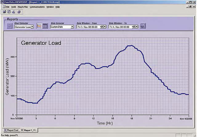
The Multilin 889 generator protection relay provides comprehensive generator monitoring and diagnostics, including a generator health report that provides an easy-to-read snapshot of a generator's health and operating condition. Based on graphical representation and trend values of the generator historical data, the 889 enables operators and asset managers to identify process issues and maintenance requirements before damage occurs and costly repairs are required.
Feeder Monitoring & Diagnostics
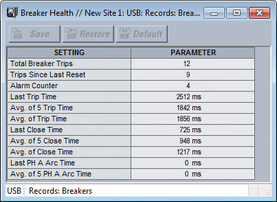
Feeder and breaker health monitoring and diagnostics are available in the Multilin 850 feeder protection relay. The 850 provides high accuracy metering and recording for all AC signals. Voltage, current, and power metering are built into the relay as a standard feature. Current and voltage parameters are available as total RMS magnitude, and as fundamental frequency magnitude and angle. The 850 also delivers comprehensive data logging, trip and close circuit monitoring elements, and a breaker arcing current element.
Communications
The 8 Series provides advanced communications technologies for remote data and engineering access, making it easy and flexible to use and integrate into new and existing infrastructures. Direct support for copper/fiber optic Ethernet provides high-bandwidth communications allowing for low-latency controls and high-speed file transfers of relay fault and event record information. The 8 Series also supports two independent IP addresses providing high flexibility for the most challenging of communication networks.
Providing several Ethernet and serial port options and supporting the widest range of industry standard protocols, the 8 Series enables easy, direct integration into DCS and SCADA systems. The 8 Series supports the following protocols:
- IEC 61850 (8 Clients, 4 Logical Devices, Tx & Rx expansion, Analog GOOSE), IEC 62439 / PRP
- DNP 3.0 serial, DNP 3.0 TCP/IP, IEC 60870-5-103, IEC 60870-5-104
- Modbus RTU, Modbus TCP/IP
The 8 Series has two interfaces as USB front port and Wi-Fi for ease of access to the relay.
- Simplify set-up and configuration
- Simplify diagnostic retrieval
- Eliminate personnel in front of switchgear
- WPA-2 security
Cyber Security
The Multilin 8 Series platform relays feature cyber security capabilities that enable the devices to deliver full cyber security data classification by security level using statures that help operators to comply with NERC CIP guidelines and regulations.
AAA Server Support (Radius/LDAP)
Enables integration with centrally managed authentication and accounting of all user activities and uses modern industry best practices and standards that meet and exceed NERC CIP requirements for authentication and password management.
Role Based Access Control (RBAC)
Efficiently administrate users and roles within UR devices. The new and advanced access functions allow users to configure up to five roles for up to eight configurable users with independent passwords. The standard “Remote Authentication Dial In User Service” (Radius) is used for authentication.
Event Recorder (Syslog for SEM)
Capture all cyber security related events within a SOE element (login, logout, invalid password attempts, remote/local access, user in session, settings change, FW update, etc), in standard Syslog data format. This will enable integration with established SEM (Security Event Management) systems.
Software & Configuration
The EnerVista™ suite is an industry-leading set of software programs that simplifies every aspect of using the Multilin 8 Series relays. EnerVista provides all the tools to monitor the status of the protected asset, maintain the device and integrate the information measured by the Multilin 8 Series, into SCADA or DCS process control systems. The ability to easily view sequence of events is an integral part of the setup software, as postmortem event analysis is critical to proper system management.
The setup tools within EnerVista Launchpad allow for the configuration of devices in real-time, by communicating via serial, Ethernet or modem connections, or offline by creating device setting files to be sent to devices at a later time.
Learn more about EnerVista Software.
8 Series Setup Software
8 Series Setup Software is single setup and configuration tool across the platform and can reduce device setup and configuration time.
Recommended Products & services
Multilin 3 Series
The 3 Series family of protection relays are functional and economical protection...
View More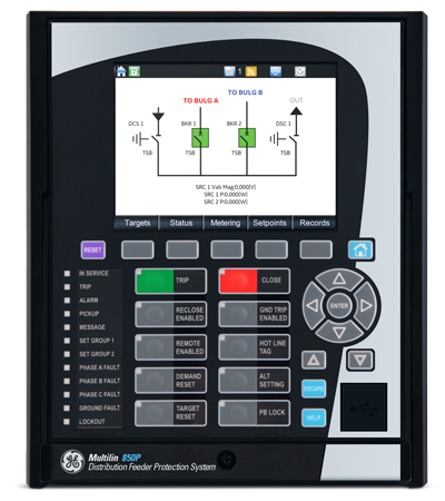
Multilin 8 Series
The Multilin™ 8 Series platform of advanced protection and control relays delivers...
View More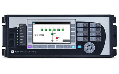
Multilin UR Family
The Universal Relay family of protection and control products are built on a common...
View MoreMultilin 750/760 - Legacy
Feeder Protection System
Manufacturing for 750/760 has been discontinued. As an alternative, please refer to the 850.
Multilin 750/760 - Legacy
Feeder Protection System
Manufacturing for 750/760 has been discontinued. As an alternative, please refer to the 850.
Key Features
- Directional time, instantaneous phase overcurrent protection
- Directional time, instantaneous ground overcurrent protection
- Directional sensitive ground and Restricted Earth Fault protection
- Negative sequence overcurrent protection
- Bus and line undervoltage
- Overvoltage
- Neutral overvoltage
- Underfrequency/Frequency decay
- Reverse power protection
- Synchrocheck
- Automatic bus transfer
- Manual control
- Cold load pickup control
- Power factor control
- 4 shot recloser (760 only)
- Power factor control
- Synchrocheck - V, f, Hz, & dead-source
Protection and Control
The 750/760 Feeder Protection System is a digital relay intended for the management and primary protection and control of distribution feeders. This easy to use relay provides comprehensive protection functions for feeders and back up protection for bus, transformers and transmission lines at a reduced product life cycle cost.

EnerVista Software
The EnerVista™ Suite is an industry-leading set of software programs that simplifies every aspect of using the 750/760 relay. The EnerVista™ suite provides all the tools to monitor the status of your protected asset, maintain the relay, and integrate information measured by the 750 into DCS or SCADA monitoring systems. Convenient COMTRADE and Sequence of Events viewers are an integral part of the 750 Setup software included with every 750 relay, to carry out postmortem event analysis to ensure proper protection system operation.
Learn More![]()

Key Features
- Metering - current,voltage, sequence components, power, energy, voltage
- Breaker operation & trip failure
- Event recording - 128 time tagged events
- Total breaker arcing current
- Ambient temperature /analog transducer input
- Analog transducer input
- Oscillography & Data Logger - 10 records up to 32 power cycles
- Simulation mode and playback capability.
Monitoring and Metering
The 750/760 features advanced monitoring and metering functions which include:
Fault Locator
The relay uses captured data to calculate the type, distance to and the impedance of the fault. Records of the last 10 faults are stored.
Breaker Conditions
The relay calculates the per-phase wear on the breaker contacts to establish a threshold. When the breaker maintenance threshold is exceeded the relay can trigger an alarm. An alarm is also generated if the relay detects that the supervisory trickle current is not present. A failure to respond to an open or close signal in a programmed time can be used to generate an alarm.
VT Failure
The VT failure feature monitors each phase of input voltage, generating an alarm and sending the programmed output signals when a failure is detected.
Analog Inputs
Any external quantity may be monitored via an auxiliary current input. Two analog input level monitoring elements and two rate-of-change elements are available. When the measured quantity exceeds the pickup level, the relay can trigger an alarm or signal an output.
Event Recording
The relay captures and stores the last 512 events, recording the time, date, cause, and system parameters. Events may be recorded selectively by category, so that only events of interest are recorded.
Oscillography
A block of configurable volatile memory can be used for recording samples of the AC input voltages and current, and the status of logic inputs and output relays. This memory can be configured between the ranges of two to 16 blocks with 16 to 256 power frequency cycles of data respectively. The amount of pre-event data recorded is set by the user. Trace memory recording can be triggered by operation of selected features or logic inputs.
Trip Counter
The number of breaker trip operations is recorded, and can be displayed for statistical purposes (useful for units without operation counters).
Key Features
- Networking interfaces - 10Mbps Ethernet, RS232, RS485 and RS422 ports
- Ethernet port, 10Mbps
- Multiple protocols - ModBus™ RTU, ModBus™ RTU, TCP/IP, DNP 3.0 Level 2
Advanced Communications
The 750/760 is equipped with three standard serial communications ports, one RS232 located in the front panel, and two RS485/RS422 in the rear of the relay. A rear Ethernet port is also available as an optional feature. The front panel port allows easy local computer access. The rear ports provide remote communications or connection to a DCS, SCADA, or PLC. The baud rate of all the serial ports is variable from 300 to 19,200 bps. The optional Ethernet port can be used to connect the 750/760 to 10 Mbps Ethernet networks. The 750/760 supports ModBus® RTU, DNP3.0 Level 2, and ModBus® RTU TCP/IP protocols.
The three serial ports support ModBus® RTU protocol, while any one of the two rear ports but not both can be configured to support DNP 3.0 Level 2. The optional Ethernet port supports ModBus® RTU via TCP/IP protocol. The communication system of the 750/760 is designed to allow simultaneous communication via all ports.
Using Ethernet as the physical media to integrate the 750/760 to Local or Wide Area Networks, replaces a multipoint wired network (e.g., serial Modbus®), and eliminates expensive leased or dial-up connections, reducing monthly operating costs.
User Interface
Various user interfaces facilitate operation of the 750.
Display
A 40 character display allows access to setpoints, actual values, and diagnostic messages generated by a trip or alarm condition. The 750 can display 30 user-selected messages during keypad inactivity.
Indicators
Twenty LEDs indicate relay status, system status, and trip and alarm conditions.
IRIG-B Input
This feature provides time synchronization via standard GPS clock inputs.
EnerVista Software
The EnerVista™ Suite is an industry-leading set of software programs that simplifies every aspect of using the 750/760 relay. The EnerVista™ suite provides all the tools to monitor the status of your protected asset, maintain the relay, and integrate information measured by the 750 into DCS or SCADA monitoring systems. Convenient COMTRADE and Sequence of Events viewers are an integral part of the 750 Setup software included with every 750 relay, to carry out postmortem event analysis to ensure proper protection system operation.
Learn More![]()
Retrofit Kit
 Explore the 8 Series Retrofit Kit
Retrofit Existing SR 750 Devices to the Multilin 850 in Minutes
Traditionally, retrofitting an existing relay has been a challenging, time consuming task often requiring re-engineering, new drawings, panel modifications, re-wiring and re-testing.
The 8 Series Retrofit Kit provides a quick, 3-step solution to upgrade previously installed SR 735 or SR 750/760 Devices. With the new 8 Series Retrofit Kit users are able to install the 850 Feeder Management System without modifying existing cutouts and wiring, and without any drawing changes or re-engineering time.
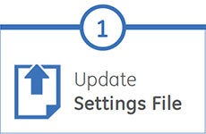
Easy 3-Step Process to Upgrade in as Fast as 21 Minutes

EnerVista 8 Series Setup Software provides automated setting file conversion. Once completed, a graphical report is provided to verify and call out any specific settings that may need attention.

Simply remove the terminal blocks and then remove the SR chassis from the panel. No need to disconnect any of the field wiring.

Insert the new 8 Series Retrofit chassis into the switchgear and simply plug-in the old terminal blocks - there is no need to make any cut-out modifications or push and pull cables.
Recommended Products & services
Feeder Protection
GE Vernova’s distribution feeder protection systems provide advanced protection with...
View MoreMultilin 745 - Legacy
Transformer Protection System
High-speed, draw-out transformer protection and management
Manufacturing for 745 has been discontinued. As an alternative, please refer to the 845 relay
Multilin 745 - Legacy
Transformer Protection System
High-speed, draw-out transformer protection and management
Manufacturing for 745 has been discontinued. As an alternative, please refer to the 845 relay
Key Features
- Variable dual-slope percent differential protection
- Magnetizing inrush and overexcitation blocking
- Phase & ground overcurrent elements
- Adaptive time overcurrent using FlexCurves elements
- Underfrequency/Overfrequency Protection
- Frequency rate-of-change Detection
- Overexcitation (V/Hz) Protection
- Restricted Ground Fault Protection
- Transformer overload protection
Protection & Control
The 745 Transformer Protection System is a full featured transformer protection relay, suitable for application on small, medium, and large power transformers. The 745 can be applied on two-winding and three-winding transformers, and can be applied on transformers with breaker-and-a-half source terminals. Multiple current and voltage inputs are used to provide primary protection, control and back-up protection of transformers, including current differential, Restricted Ground Fault neutral, and ground overcurrent, over-fluxing, and on-load tap changer. The 745 also has specific features for industrial environments, including a drawout case to limit downtime during maintenance and conformal coating for harsh environments. The 745 also includes analog inputs and outputs, while incorporating advanced features such as transformer loss of life monitoring.
Key Features
- Metering - current, voltage, sequence components per winding, power, energy, voltage
- THD and harmonics up to the 21st
- Expanded (doubled) sequence of event recorder and waveform capture (256 time stamped events and
up to 128 cycles of oscillography data at a sampling rate of 64 samples per power cycle) - Tap position up to 50 tap positions
- Ambient temperature /analog transducer input
- Analog transducer input
- Oscillography & Data Logger - 10 records up to 32 power cycles
- Simulation mode and playback capability.
Monitoring & Metering
The 745 features advanced metering functions including:
Currents All current inputs feature harmonic level detectors. A sampling rate of 64 times the power cycle allows recovery up to the 21st harmonic. Total Harmonic Distortion (IEEE.519-1986) or Harmonic Derating Factor (as per ANSI/IEEE C57.110-1986) are calculated for each winding and compared against user-adjustable setpoints.
Asset Monitoring
745 can monitor, calculate and log hottest-spot temperature, aging factor and lost of life data over a long period. These data combined with economic analysis, allows criteria to be developed regarding the best time at which to replace a power transformer due to load growth, i.e. to minimize the cost without significantly increasing the risk.
Event Recording
The last 128 events are captured and stored, recording the time, date, cause, and system parameters of each event. This information is easily accessible by computer via communication port or the front panel display.
Tap Position, Ambient Temperature, Analog Transducer-Input
The 745 monitors and displays tap position and ambient temperature. An optional general purpose transducer input allows a user-defined quantity to be monitored and used as part of the protection as defined by FlexLogic™.
Simulation Mode
Simulation Mode allows testing the functionality of the relay by simply feeding arbitrary waveform data into the relays simulation buffer for playback as sampled current input signals.
Fault Recording
System input signals are sampled at a rate of 64 times the power cycle. Because all the signals are sampled at the same instant in time the magnitude and phase relationship of each can be compared. A combination of 16 pre and post-trigger cycles can be saved.
 Analyze generator faults using waveforms that are captured at the time of generator faults or system instabilities
Advanced Automation
The 745 incorporates advanced automation features including powerful FlexLogic™ programmable logic, communication, and SCADA capabilities that far surpass what is found in the average line relay. The 745 integrates seamlessly with other relays for complete system protection.
Key Features
- Networking interfaces - 10Mbps Ethernet, RS232, RS485 and RS422 ports
- Ethernet port, 10Mbps
- Multiple protocols - ModBus™ RTU, ModBus™ RTU TCP/IP, DNP 3.0 Level 2
- Fast, flexible and reliable communications - Embedded 10BaseT Ethernet capability provides faster data
transfer thus improves system performance
Advanced Communications
The 745 is equipped with three standard serial communications ports, one RS232 located in the front panel, and two RS485/RS422 in the rear of the relay. One optional Ethernet port is available at the rear of the relay. The front panel port allows easy local computer access. The rear ports provide remote communications or connection to a DCS, SCADA, or PLC. The baud rate of all the ports is variable from 300 to 19,200 bps. The optional Ethernet port can be used to connect the 745 to 10 Mbps Ethernet networks. The 745 supports ModBus® RTU, DNP3.0 Level 2, and ModBus® RTU TCP/IP protocols.
The three serial ports support ModBus® RTU protocol, while either of the two rear ports can be configured to support DNP 3.0 Level 2. The optional Ethernet port supports ModBus® RTU via TCP/IP protocol. The communication system of the 745 is designed to allow simultaneous communication via all ports.
Using Ethernet as the physical media to integrate the 745 to Local or Wide Area Networks, replaces a multipoint wired network (e.g., serial Modbus®), and eliminates expensive leased or dial-up connections, reducing monthly operating costs.
User Interface
Various user interfaces facilitate operation of the 745.
Display
A 40 character display allows access to setpoints, actual values, and diagnostic messages generated by a trip or alarm condition. The
745 can display 30 user-selected messages during keypad inactivity.
Indicators
Twenty LEDs indicate relay status, system status, and trip and alarm conditions.
IRIG-B Input
This feature provides time synchronization via standard GPS clock inputs.
EnerVista™ Software
The EnerVista™ Suite is an industry-leading set of software programs that simplifies every aspect of using the 745 relay. The EnerVista™ suite provides all the tools to monitor the status of the transformer, maintain the relay, and integrate information measured by the 745 into DCS or SCADA monitoring systems. Convenient COMTRADE and Sequence of Events viewers are an integral part of the745 Setup software included with every 745 relay, to carry out postmortem event analysis to ensure proper protection system operation.
Learn More![]()

Recommended Products & services
Transformer Protection
GE Vernova's transformer protection devices provide innovative solutions for the...
View More735/737 - Legacy
Manufacturing for this product has been discontinued.
735/737 - Legacy
Manufacturing for this product has been discontinued.
EnerVista 8 Series Setup Software provides automated setting file conversion. Once completed, a graphical report is provided to verify and call out any specific settings that may need attention.
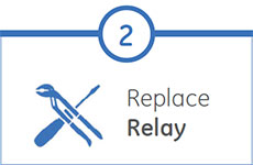
Simply remove the upper, lower and low voltage terminal blocks and then remove the SR chassis from the panel. No need to disconnect any of the field wiring.
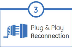
Insert the new 8 Series Retrofit chassis into the switchgear and simply plug-in the old terminal blocks - there is no need to make any cut-out modifications or push and pull cables.
Recommended Products & services
Feeder Protection
GE Vernova’s distribution feeder protection systems provide advanced protection with...
View MoreBiTRONICS 70 Series - Legacy
Measurement System
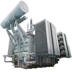
The BiTRONICS 70 Series Measurement System is an efficient, cost-effective substation automation solution for real-time monitoring and event recording. The BiTRONICS 70 Series Measurement System is a substation automation solution designed to satisfy AC network operators’ needs for real-time monitoring and event tracking. It is also an ideal system to help them protect their investments.
BiTRONICS 70 Series - Legacy
Measurement System
The BiTRONICS 70 Series Measurement System is an efficient, cost-effective substation automation solution for real-time monitoring and event recording. The BiTRONICS 70 Series Measurement System is a substation automation solution designed to satisfy AC network operators’ needs for real-time monitoring and event tracking. It is also an ideal system to help them protect their investments.
Recommended Products & services

515 Blocking and Test Module - Legacy
Sales of this product have been discontinued.
As an alternative, please refer to the
MMLB and MMLG or P991 14-way injection test blocks and P992/3.
515 Blocking and Test Module - Legacy
Sales of this product have been discontinued.
As an alternative, please refer to the
MMLB and MMLG or P991 14-way injection test blocks and P992/3.