CFD High Speed Differential Relay - Legacy
Manufacturing for CFD has been discontinued.
CFD High Speed Differential Relay - Legacy
Manufacturing for CFD has been discontinued.
Recommended Products & services
CEYG – Legacy
Reactance and Mho Phase Directional – Distance Relay
Manufacturing for CEYG has been discontinued . As an alternative, please refer to D60 or P443.
CEYG – Legacy
Reactance and Mho Phase Directional – Distance Relay
Manufacturing for CEYG has been discontinued . As an alternative, please refer to D60 or P443.
Recommended Products & services
CEY Reactance and Mho Phase Directional-distance - Legacy
Manufacturing for this product has been discontinued. As an alternative, please refer to the 3 Series relays.
CEY Reactance and Mho Phase Directional-distance - Legacy
Manufacturing for this product has been discontinued. As an alternative, please refer to the 3 Series relays.
Recommended Products & services
CEX Angle Impedance Relay - Legacy
Manufacturing for this product has been discontinued. As an alternative, please refer to the 3 Series relays.
CEX Angle Impedance Relay - Legacy
Manufacturing for this product has been discontinued. As an alternative, please refer to the 3 Series relays.
Recommended Products & services
CEH Loss of Excitation Relay - Legacy
Manufacturing for CEH has been discontinued.
CEH Loss of Excitation Relay - Legacy
Manufacturing for CEH has been discontinued.
Recommended Products & services
CEB Offset Mho Directional-distance - Legacy
Manufacturing for this product has been discontinued. As an alternative, please refer to the 3 Series relays.
CEB Offset Mho Directional-distance - Legacy
Manufacturing for this product has been discontinued. As an alternative, please refer to the 3 Series relays.
Recommended Products & services
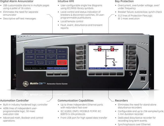
C90Plus - Legacy
Manufacturing for C90Plus Bay Controller has been discontinued. As an alternative, please refer to the C60 with Firmware 7.7 or newer and User Interface Option E: 7” Graphical Front Panel Display.
C90Plus - Legacy
Manufacturing for C90Plus Bay Controller has been discontinued. As an alternative, please refer to the C60 with Firmware 7.7 or newer and User Interface Option E: 7” Graphical Front Panel Display.
Key Features
- Dedicated automation controller with 4000 lines of logic
- Powerful math, control and Boolean operators
- Multiple stages for under/over and rate of frequency protection for load shedding
- Dedicated protection logic at 1 msec execution rate
- Dedicated HMI for breaker and disconnect control
- Multi-breaker synchrocheck with single/three-pole autoreclosing
- Dual-breaker failure protection
- Direct and teleprotection elements using the inter-relay communication card
- CT and VT monitoring
- Metering – current, voltage, frequency, power, energy and phasors
- Fault recorder – 256 samples/cycle, 30 sec of storage capacity
- Disturbance recorder – 1 sample/cycle, 5 min of storage capacity
- Event recorder – 8000 time tagged event, with 0.5 ms scan of digital inputs
- Comprehensive display of metering, phasors, maintenance and fault information in the front panel
Advanced Bay Control
The C90Plus bay control or monitoring functionality is intended for high-end bay control applications typically used in transmission installations, where a larger quantity of I/O, advanced protection and control functionality and an advanced HMI is desired.
- Advanced bay control and interlocking
- Breaker monitoring and control
- Automatic Bus Transfer schemes
- Load shedding and load restoration schemes
Fast Load Shed Benefits
- Fast optimal load shedding executed within 20ms
- Intelligently sheds loads to maintain system/process integrity
- Highly customizable and scalable, integrating easily into most industrial plants with new or existing EMS/SCADA
- Optional stand-alone system with local HMI for viewing dedicated system status and reports
- Suitable for small or large industrial systems without re-design
Easy to use system where settings and priorities can be configured within seconds
Fast Load Shed
Conventional frequency and voltage load shedding schemes operate typically between 250ms to seconds. Contingency-based load shedding schemes are typically faster at 160 – 400 ms, depending on both system architecture and communications employed. Both these scheme types are too slow for industrial cogeneration applications such as oil and gas or manufacturing, where very fast load shedding is required for power system and critical process integrity.
 Digital fault recorder summary with the latest information on the events, faults, transients and disturbances.
Recording capability
There are three recorders available within the C90Plus that eliminate the need for other stand-alone recording equipment. The transient recorder allows for a high sampling rate usually to capture power system faults and system transients. The disturbance recorder is used to capture longer records in order to understand issues such as voltage sags or swells. Lastly, the C90Plus is equipped with a powerful and accurate Sequence of Event (SOE) recorder. Information for all three recorders can be accessed either through the front panel HMI or through EnerVista™ Launchpad Software.
Deterministic automation
- Dedicated automation controller with 4000 lines of logic at a deterministic 50 msec execution rate
- Powerful math, control and Boolean operators to support the automation logic engine
- 10 stages of under/over frequency protection for load shedding
- 4 stages of rate of change of frequency for load shedding
- 6 stages of under-voltage elements for load shedding
 The C90Plus supports an advanced automation logic engine that supports Boolean operators, analog comparisons, and advanced mathematical operations.
Key Features
- HMI can show fault reports to local operators, enabling quick access to time sensitive information
- Customizable annunciator panel, capable of handling up to 288 alarms using a pallet of 16 colors
- Front panel display of results from the self-tests performed, allowing easy maintenance and viewing of critical indications
- Access product information, such as IP addresses and serial numbers, without the need to connect to the unit
- Increase network availability by reducing failover time to zero through IEC62439-3 “PRP” support
- IP addresses and serial numbers of each module are also accessible without the need to connect to the unit
- Full color customizable local HMI allowing easy and secure control
- HMI-equipped with pre-built screens or configurable to display any single diagram
- Reliable communication card with automatic failover and extremely fast redundant schemes
- Inter-relay communication card enables implementation of pilot schemes based on standard communication protocols
- Both “Direct” and “Teleprotection” I/O elements
Advanced communications
The C90Plus provides for secure remote data and engineering access, making it easy and flexible to use and integrate into new and existing infrastructures. Fiber optic Ethernet provides high-bandwidth communications allowing for low-latency controls and high-speed file transfers of relay fault and event record information. The availability of three independently configurable Ethernet options provide the means to create fault tolerant communication architectures in an easy, cost-effective manner. The C90Plus supports the most popular industry standard protocols enabling easy, direct integration into SCADA systems.
- IEC 61850
- DNP 3.0
- Ethernet Global Data (EGD)
- IEC 60870-5-104
- Modbus RTU, Modbus TCP/IP
- PRP as per IEC 62439-3
Key Features
HMI Display
- Display fault reports and self-test results, enabling quick access to time sensitive information
- Customizable annunciator panel, capable of handling up to 288 alarms using a pallet of 16 colors
- Access product information, such as IP addresses and serial numbers, without the need to connect to the unit
- HMI equipped with pre-built screens or could be configured to display any single diagram
Security
- Dual permission access, requiring live permission from both the user and from SCADA operators
- Remote and local setting and control passwords
- Configurable lockouts to unsuccessful password access attempts
- Successful password access logged in Events Record
- Logging of user commands in the security audit trail report creates a record and sequence of events log for troubleshooting and security auditing
Enervista software
The EnerVista™ suite is an industry-leading set of software programs that simplifies every aspect of using the C90Plus relay. The EnerVista™suite provides all the tools to monitor the status of the protected asset, maintain the relay, and integrate information measured by the C90Plus into DCS or SCADA monitoring systems. Convenient COMTRADE and Sequence of Events viewers are an integral part of the UR setup software included with every UR relay, to carry out postmortem event analysis and ensure proper protection system operation. Learn More
Security - enabling NERC CIP compliance
Access Control
Multilin devices and relays are designed with simple but powerful security to enable reliability and compliance for virtually any project or implementation. With support for multi-level permissions and multi-factor supervisory controls, Multilin devices can help you manage the integrity of your system during commissioning, testing, implementation, and beyond. The UR and URPlus families provide separate authentication for settings and commands to the system. In addition, as discrete authentications for local and remote access they also provide supervisory control factor that can lock or unlock a device for configuration changes and other modifications.
Intrusion Detection
Multilin’s family of protection and control products can also help enable your security perimeter and intrusion detection programs. By providing essential alarming and logging of critical events, Multilin devices can help you detect potential breaches within your system and allow you to respond quickly and effectively. Specifically, unsuccessful access attempts are logged, alarmed, and lead to potential attackers being locked out. This ensures the reliability of your system during questionable activity, and a control factor that can lock or unlock a device for configuration changes and other modifications.

Auditing and Reporting
With the security audit trail reporting feature and support for event logging of key activities such as configuration changes, Multilin devices can help ensure device and protection system integrity, and perform forensic auditing of activities and changes for compliance.

Fast Load Shed
The C90Plus Automation Control System with fast load shed is a powerful automation control system that eliminates the need for several separate devices. Performing intelligent high-end and fast optimal load shedding, the C90Plus is highly customizable and scalable.

Communications & HMI
- Enhanced HMI and annunciator panels on the front of the C90Plus make it one of the most powerful human machine interfaces on local units
- Three new Inter-Relay Communication (IRC) cards enable the URPlus devices to support pilot-schemes based on standard communication protocols, and both “Direct” and “Teleprotection” inputs and output elements are available. The IRC cards can work on either schemes that demand direct URPlus-to-URPlus connection or schemes that have specialized communication devices between the line terminals (multiplexers, microwave, etc).
- PRP as per IEC 62439-3

Protection
New small signal oscillation detection protection element. With increasingly large interconnected power systems, one of the technical challenges is the inter-area low frequency oscillations. Inter-area oscillations not only limit the amount of power transfer, but also threaten system security and equilibrium, as they may lead to system instability and cascading outages. Therefore, it is essential to identify the characteristics of the inter-area oscillations, including oscillation frequency and damping ratio, so that proper actions can be taken based on the results. This is required to improve system damping and maintain stability in the power system. The C90Plus can detect these inter-area oscillations and provide an alarm or even trip signal to prevent a large-scale system disturbance.

Security Enhancements - Enabling NERC CIP compliance:
Support for alphanumeric passwords as per the CIP-007-02 cyber security standard.
Recommended Products & services

Line Protection
GE Vernova's transmission protection solutions deliver the speed and security necessary...
View MoreBUS1000/2000 Bus Bar Protection
The BUS 1000/2000 is a solid state, high speed protection system for the detection of phase-to-phase and phase-to-ground faults on bus bar installations. It can be used to protect high voltage bus bar installations of any voltage.
BUS 2000 models add to the functionality of the BUS 1000 through the metering, monitoring, event recording, waveform capture, and IRIG-B time synchronization capabilities of the DMS metering and monitoring module.
BUS1000/2000 Bus Bar Protection
The BUS 1000/2000 is a solid state, high speed protection system for the detection of phase-to-phase and phase-to-ground faults on bus bar installations. It can be used to protect high voltage bus bar installations of any voltage.
BUS 2000 models add to the functionality of the BUS 1000 through the metering, monitoring, event recording, waveform capture, and IRIG-B time synchronization capabilities of the DMS metering and monitoring module.
Recommended Products & services

Bus Protection
GE Vernova provides enhanced reliability through advanced protection for a wide range of...
View MoreBDD Percentage Differential with Harmonic Restraint
The Type BDD relays are for the protection of transformers rated 2000 kVA and above and for transformers with windings rated 15 kV or above. However, the importance of the transformer to the system, not its size alone, should be the basis for the decision on this quality of protection.
Applications
- Power and autotransformer protection
Protection and Control
- High speed percentage differential
- Phase and ground fault detection
- Current restraint circuits available
BDD Percentage Differential with Harmonic Restraint
The Type BDD relays are for the protection of transformers rated 2000 kVA and above and for transformers with windings rated 15 kV or above. However, the importance of the transformer to the system, not its size alone, should be the basis for the decision on this quality of protection.
Applications
- Power and autotransformer protection
Protection and Control
- High speed percentage differential
- Phase and ground fault detection
- Current restraint circuits available
Recommended Products & services
B95Plus – Legacy
Manufacturing for this product has been discontinued.
B95Plus – Legacy
Manufacturing for this product has been discontinued.
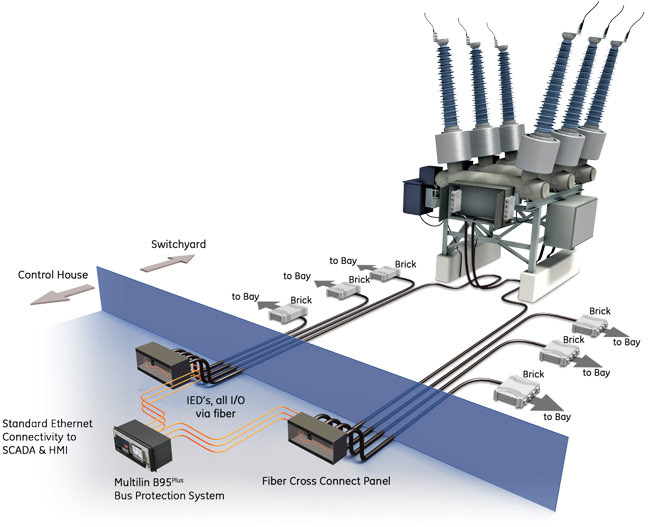
Field Wiring
We Solve the Field Wiring Challenge with the B95Plus Bus Protection System
The Multilin B95Plus Bus Protection System changes the focus of bus protection to that of application by replacing most of the field wiring with distributed I/O and fiber optic cables. The bus protection system consists of a distributed process interface (data acquisition and tripping) architecture using HardFiber Bricks as bay units, with centralized processing performed by the B95Plus protection relay. All copper field wiring is between primary equipment in the switchyard and Bricks, which ideally should be located at the primary equipment in the switchyard. Fiber optic cables connect Bricks to the B95Plus. For all applications, the installation is then identical: the physical interface consists of Bricks connected to a fiber optic cable. A single B95Plus is mounted in a relay cabinet, with the process cards in the unit patched to the fiber optic cables coming from the Bricks.
HardFiber Brick System
The HardFiber Brick System can easily be incrementally scaled to include new equipment as stations evolve. Duplicated Bricks in the switchyard provide a drastic improvement in reliability and security over today’s technology.
Hardware
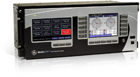
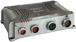
Multilin B95Plus Bus Protection Relay
The B95Plus bus protection relay unit is the heart of the system. This unit performs all processing functionality, including protection functions, metering, monitoring, FlexLogic and SCADA communications.
- Simplifies use through a Graphical User Interface (GUI) that includes configurable single line diagrams for bus sources, local control and status indication of breakers and disconnects, 20 programmable pushbuttons, and a configurable digital alarm annunciator
- Connects up to 8 Bricks for each process card while, supporting up to 12 bus sources per card
- Supports 2 process cards per unit, for a total of 16 Bricks and 24 bus sources
- Provides identical connections and installation for all bus configurations
HardFiber Brick as Bay Unit
- Measurement and control for primary apparatus, including AC measurements (4 currents and 4 voltages, or 8 currents) and contact I/O (18 digital inputs and 7 digital outputs including a latching relay)
- Simple device with no field configuration or configuration settings
- Environmentally hardened for outdoor mounting in switchyards
- Connectorized cables for simple, tools-free field installation and removal
- IEC 61850 message formats for communications, including sampled value messaging for currents and voltages
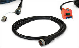
Cables
The HardFiber Brick uses connectorized cables to interface with primary equipment and with system measurements, and to interface to the B95Plus itself. The cables at the Brick end uses an IP67 certified industry standard connector designed for rugged environments. These connectors screw onto the Brick for a simple, tools-free connection. Three of the cables are copper cables used to acquire AC measurements, acquire equipment status, and provide equipment control. The fourth cable provides the fiber interface to the B95Plus central unit as well as DC power to the Brick. These cables therefore can become standard parts, manufactured in advance of installation by any cable manufacturer. These cables are also directly available from GE Vernova.
Protection
The B95Plus bus protection relay system provides robust and reliable protection for all bus protection applications. Highlights of the protection functions related to bus protection include:
- Multi-zone differential protection with both restrained (dual-slope percent or biased) and unrestrained (unbiased or instantaneous) functions incorporated.
- Differential protection is fast (typical response time: 1 power system cycle) and secure. Security is achieved by using a fast and reliable CT saturation detection algorithm and a phase comparison operating principle. Security is further enhanced by support for redundant process interface units (Bricks). Supports both three-phase tripping and individual phase tripping.
- Dynamic bus replica functionality and multi-zone protection (up to 6 zones) is supported allowing application of the B95Plus to multi-section reconfigurable buses. A zone expansion/contraction to an open breaker feature is included. Isolator position monitoring for up to 48 isolators.
- Check-zone functionality configured by programming one of the differential zones to enclose the entire bus.
- Additional bus protection functions including end fault protection, breaker fail and overcurrent protection for each bus source, CT trouble monitoring for each bus zone.
Multilin B95Plus Functional Block Diagram
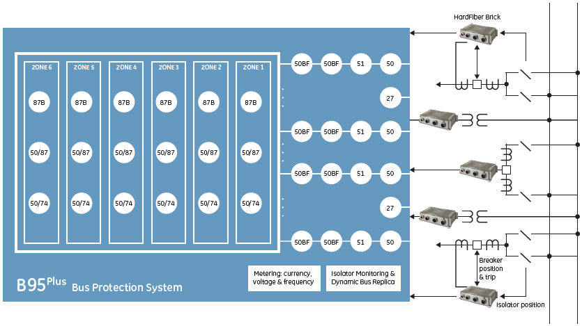
ANSI Divice Numbers & Functions
| Device Number | Function |
|---|---|
| 87B | Percent bus differential |
| 27 | Undervoltage |
| 50 | Instantaneous overcurrent |
| 50/74 | CT Trouble |
| Device Number | Function |
|---|---|
| 50/87 | Unrestrained Bus Differential |
| 51EF | End fault protection |
| 51 | Time overcurrent |
| 50BF | Breaker failure |
Applications
- Reconfigurable multi-section bus bar with up to 24 feeders
- Retrofit and greenfield installations for power generation, transmission and distribution systems
- Reconfigurable bus bars for single bus, breaker-and-a-half and double bus with and without bus couplers
- Air-insulated and GIS stations
Standardize on the B95Plus for Any Bus Configuration
The B95Plus can be applied on a multitude of bus configurations due to the distributed architecture, and includes support for up to 6 zones of bus differential protection and support for up to 24 bus sources. The physical connection and wiring architecture for the B95Plus system will be identical for any bus configuration: Bricks installed to acquire measurements and equipment status, with the B95Plus unit connected to Bricks via fiber optic cables. The relay panel design will be identical for all applications, for all bus configurations. The only difference from application to application is the number and location of Bricks, and the programming of the B95Plus unit.
Some typical bus configurations that can be protected by the B95Plus:
 Two single buses with a bus coupler
 Double bus with a bus coupler
 Breaker-and-a-half arrangement
Process Bus
Quickly Expand Protection through Process Bus
The B95Plus Bus Protection System is intended to operate as a standalone, distributed bus protection system. The bay units for this system are Bricks, part of the HardFiber IEC 61850 process bus solution. Once the Bricks for the B95Plus are installed process bus data is available for use for any other zone of protection. The Bricks, then, are a distributed I/O interface for all protection functions and zones, not just the B95Plus. With the B95Plus in place, installing line protection or feeder protection is a simple process: mount the relays in a panel, and patch to the fiber optic cable from the appropriate Bricks. The only requirement is the relays must implement the appropriate IEC 61850 datasets to interface successfully with the Bricks. All members of the Universal Relay family have the ability to interface with Bricks.
 Expand protection through process bus
Specifications
| BUS DIFFERENTIAL PROTECTION | |
|---|---|
| Number of differential zones | Six 3-phase zones |
| Max number of currents: | Total dynamic number of bus source to zone connections closed at any one moment in time up to 120 |
| CT ratio compensation range | 32:1 |
| Operating time | < 1 power system cycle - typical bus fault |
| BUS REPLICA | |
|---|---|
| Features | Dynamic bus source current assignment to each zone, dynamic zone trip assignment to each bus source, dynamic blocking of zones on CT bypassed, 1 user programmable auxiliary zone trip inputs, 3 user programmable bus source trip inputs, dynamic zone expansion/reduction |
| BUS SOURCES | |
|---|---|
| Number of bus sources | 12 per process card included in the order code |
| Current inputs | 3-phase currents |
| CT rated primary | 1 to 65000 A |
| CT rated secondary | 1 A or 5 A |
| Nominal frequency | 50 or 60 Hz |
| CT Trouble Monitoring | 1 element per bus source |
| Breaker failure protection | 1 element per bus source |
| Instantaneous Phase Overcurrent | 1 element per bus source |
| Inverse Time Phase Overcurrent | 1 element per bus source |
| VOLTAGE SOURCES | |
|---|---|
| Number of voltage sources | 2 per process card included in the order code |
| Voltage inputs | 3-phase voltages, wye or delta |
| VT ratio | 1.00 V to 24000.00 /td> |
| VT rated secondary | 25.0 V to 240.0 V |
| Nominal frequency | 50 or 60 Hz |
| ISOLATORS | |
|---|---|
| Number of isolators | 48 per process card included in the order code |
| Isolator status inputs | Form “a” and form “b” contact inputs, each optionally dual redundant |
| Configurable failsafe modes | 2Open, closed, last valid state |
| Monitoring | Alarm on inconsistent inputs persisting longer than a user set time |
| TRANSIENT RECORDER | |
|---|---|
| Storage capacity | Five records with all channels recorded, at 128 samples per cycle, spanning 1 second with no retriggers |
| Number of records | 1, 2, 5, 10, 20, 30, 40, or 50 records |
| Sampling rate | 16, 32, 64 or 128 samples per power cycle |
| AC waveform channels | All enabled bus sources and voltages sources |
| Analog channels | Magnitudes and angles of all ac waveforms recorded plus all enabled zone differential and zone restraint phase current magnitudes and angles |
| Digital channels | 128 user configurable channels on the main card and 128 user configurable channels on each process card |
| Configurable digital data | Any FlexLogic™ operand |
| Storage modes | Automatic overwrite, protected |
| Triggering modes | Time window from rising edge of trigger, continuous recording up to 4 additional basic record lengths as long as retrigger is active |
| Pre-trigger window | 0 to 100% of the basic record length |
| Data storage | non-volatile memory |
| EVENT RECORDER | |
|---|---|
| Storage capacity | 8,192 events plus 8,192 events on each process card |
| Time tag: | to 1 µs |
| Triggers | all FlexLogic™ operand activations |
| PROCESS I/O | |
|---|---|
| Number of process bus ports | 8 per process card |
| Port type | 100Base-BX-D, in SFP package with LC 50/125µm multi-mode connector |
| Transceiver diagnostics | per SFF-8472 |
| Brick synch frame jitter | ±1µs |
| POWER SUPPLY | |
|---|---|
| Nominal DC voltage | 125 to 250 V |
| Minimum DC voltage | 80 V |
| 1Maximum DC voltage | 300 V |
| Nominal AC voltage | 100 to 240 V at 50/60 Hz |
| Minimum AC voltage | 80 V at 48 to 62 Hz |
| Maximum AC voltage | 275 V at 48 to 62 Hz |
| Voltage withstand | 2 × highest nominal voltage for 10 ms |
| Voltage loss ride-through | 200 ms duration at nominal input voltage |
| Power consumption | 150 VA maximum |
| PROCESS CARD OPTICAL | |
|---|---|
| Number of transceivers | 8 |
| Transceiver type: | Transmit 1550 nm, receive 1310 nm, 100Mb/s, bi-directional single-fiber 50/125µm multi-mode module (levels comply with IEEE 802.3 standard 100Base-BX-D) |
| Optical transmit power | –14 to –8 dBm |
| Maximum optical input power | –8dBm |
| Optical receiver sensitivity | –30dBm |
| Termination | LC fiber connector |
| Laser class | Class 1. This product is eye-safe under all operating conditions. |
| REMOTE RESOURCE SPECIFICATIONS | |
|---|---|
| Number of field units | 8 per process card |
| Number of field contact inputs | 1 for each brick contact input |
| Number of field contact outputs | 1 for each brick contact output |
| Number of field latching outputs | 1 for each brick latching output |
| Number of shared inputs | 16 per process card |
| Number of shared outputs | 16 per process card |
| APPROVALS AND CERTIFICATION | |
|---|---|
| Compliance | CE, UL, ISO |
| Compliance | Applicable Council | Directive According To |
|---|---|---|
| CE | Low voltage directive | EN 60255-27 (normative sections) |
| EMC directive | EN 60255-26 / EN 50263 EN 61000-6-5 (Area G) | |
| UL | cULus | UL 508 UL 1053 C22.2 No 14 |
| ISO | Quality management system | ISO 9001 |
Recommended Products & services
Bus Protection
GE Vernova provides enhanced reliability through advanced protection for a wide range of...
View More