Protection, Control & Metering
A full portfolio of accessories to support power systems including test equipment, terminal blocks and indicator lights.
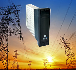
A variety of auxiliary relays including multicontact, trip and lockout, annunciator and hinged armature relays.
Not finding the product that you’re looking for? View legacy auxiliary relays products.
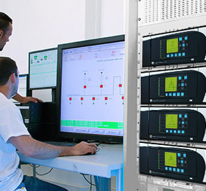
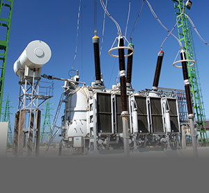
Powerful equipment for monitoring, recording and analysing electrical power systems

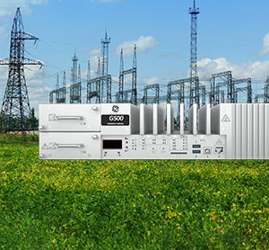
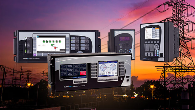
Support a wide range of inputs, outputs and communication protocols on electrical assets

Innovative solutions for the protection, control and monitoring of generator assets.
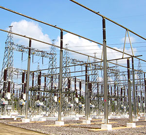
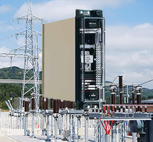
Solutions to implement IEC 61850 Process Bus and contribute to a full digital substation
Single function protection for applications including overcurrent, voltage and frequency, differential, directional, timing and distance.