Search Gas Power
Search our products, insights, and resources
Recommended resources
Upgrades
Your outcomes—delivered
These days, we're all trying to do more with less, but GE Vernova can help. Our upgrades and modernizations can help you get more from your existing assets. Discover the possibilities with our interactive upgrades selector.

Controls
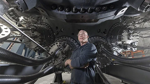
Control Lifecare Services
Whether you need 24/7 technical support, live remote diagnostics, onsite field engineering, or parts management, we have you covered with GE Vernova's Controls Lifecare Services (CLS).

Podcast
Cutting Carbon - Season 9
Join Dr. Jeff Goldmeer, Brian Gutknecht, and special guests for the final season of our 3-part series as they discuss the roles digital and electrification will play in the energy transition.

Decarbonization in action
Explore the future of energy
See how GE Vernova's Gas Power business is helping to build a world that works.
Overview
NZT Power, which aims to be the first commercial power station equipped with carbon capture and storage (CCS), is expected to generate 740+ MW to support UK's aim for net zero goals—while creating and supporting 3,000+ jobs during construction.
The challenge
Teesside is exploring how to help reduce emissions from power generation to support the UK's goal to decarbonize the power sector by 2035.
The solution
The NZT Power facility will integrate GE Vernova’s 9HA.02 gas turbine with carbon capture technology to generate low-carbon power for Northern England. As the plant powers the region, carbon abatement technology will capture up to 2 million tonnes of CO2 annually and transport it via pipeline to secure offshore storage.
Outcomes
Building the blueprint for decarbonized power
"
We are excited to collaborate with GE Vernova and Balfour Beatty on the first-of-its kind Net Zero Teesside Power project. ...This groundbreaking project represents a significant milestone in our collective efforts to help advance carbon capture technology at scale and aims to support the UK's ambitious climate goals.
Arnaud Pieton
CEO of Technip Energies
NZT Power represents a landmark effort to tackle industrial emissions while supporting the transition to a low-carbon energy future. With £22 billion in government funding dedicated to advancing CCS technologies, the project is part of a broader plan to bring more sustainable change to Teesside’s carbon-intensive industrial cluster. The facility will be powered by GE Vernova’s 9HA.02 gas turbine, a steam turbine, a generator, a Heat Recovery Steam Generator (HRSG), and an Exhaust Gas Recirculation (EGR) system, all integrated with Technip Energies' carbon capture and compression system.
A critical feature of the plant’s engineering is GE Vernova’s EGR technology, which recycles CO2-rich flue gas back to the turbine inlet. By increasing the concentration of CO2 in the exhaust, this innovative system helps reduce energy and solvent demands, and lowers overall operational costs. This integration not only boosts performance but also aims to set a benchmark for future CCS projects to achieve greater environmental and operational impact.
NZT Power is a key step toward the UK’s 2035 climate goals, showcasing how advanced technologies can help decarbonize industrial regions and reduce reliance on fossil fuels. By providing more reliable low-carbon power, the project will not only stabilize the grid but also complement the expansion of renewable energy sources, providing consistent supply even during periods of low wind or solar generation. NZT Power exemplifies the integration of cutting-edge technologies like CCS and EGR technology, making it a global model for combining innovation, efficiency, and sustainability to help drive the energy transition forward and encourage deployment of similar projects worldwide.
A closer look
How the EGR system's components work
The EGR system, part of NZT Power’s carbon capture technology, consists of several components working together to recycle flue gas from the exhaust back to the turbine inlet. Below is a step-by-step guide detailing how this process enhances operational efficiency.
Understanding the flow
Visualizing EGR: Integration across the gas turbine system
The animation above illustrates how EGR integrates into the gas turbine system. Below, we break down its impact across each key component—from inlet and flue gas mixing to controls and dampers.
- Inlet mixer: Cooled and cleaned recycled flue gas exits the EGR loop and is introduced into the inlet mixer through an entry duct. The inlet mixer is designed to thoroughly mix the recycled flue gas with ambient air.
- Gas turbine: The now blended stream of recycled flue gas and ambient air travels through the gas turbine. Due to the recycled flue gas, the gas turbine exhaust has a higher concentration of carbon dioxide than it would have without EGR.
- Heat Recovery Steam Generator (HRSG): The exhaust gas next travels through the HRSG. Instead of exiting the HRSG stack, the exhaust leaves the HRSG out of an opening in the back of the stack. At this point, the flow is divided. A majority of the flow is sent to the carbon capture facility. The balance of the flow is sent to the EGR loop.
- Dampers: A system of dampers is provided to route flue gas to the EGR and carbon capture systems. In addition, the dampers provide isolation when the EGR system is off.
- Flue gas fan: A fan drives the recycled flue gas through the EGR loop. Alternately, new units may be designed to eliminate the fan.
- Enhanced direct contact cooler: No changes except remove the extra C in (eDCC)
- Controls (not shown): The controls system has three primary functions: 1) manage startup and shutdown of the EGR system, 2) control the system during normal operations, and 3) provide protection during an unexpected event.
Contact us