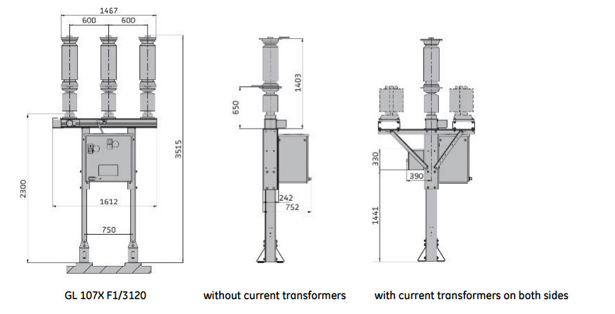
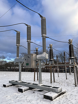
GL 107X
Live tank circuit breaker from 36 kV up to 40.5 kV
Highly Reliable Performance
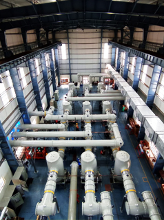
GE Vernova’s GL 107X live tank circuit breakers for outdoor installation are provided with third-generation self-blast interrupter chambers and spring-operated mechanisms. The field-proven interrupter chamber operates on the energy-optimized self-blast principle. This live tank circuit breaker provides a high level of reliability for customers, even under extreme conditions and climates or in highly active seismic areas.
GL 107X
Live tank circuit breaker from 36 kV up to 40.5 kV
Highly Reliable Performance
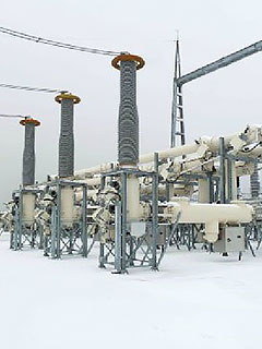
GE Vernova’s GL 107X live tank circuit breakers for outdoor installation are provided with third-generation self-blast interrupter chambers and spring-operated mechanisms. The field-proven interrupter chamber operates on the energy-optimized self-blast principle. This live tank circuit breaker provides a high level of reliability for customers, even under extreme conditions and climates or in highly active seismic areas.
High Quality Components
The GL 107X live tank circuit breaker provides high reliability based in part on high quality components, including:
- Third-generation self-blast interrupter chamber
- Operating linkages in one common gas enclosure forming part of the base frame
- Only one seal is dynamically stressed
- Insulator flanges sealed with Portland cement
- Pressure relief system for passive protection of both substation and personnel
- Compact design in line with considerations of current transformers
- Field-proven, temperature-compensated density monitor with two-stage transducer and three-color dial
- Easy access to the SF₆ filling connection (type DILO)
- Extruded aluminum base frame
- Reliable spring-operated mechanism with position indicator clearly visible from outside
Installation and Maintenance
- Preset at factory before shipping; no adjustments necessary during installation and commissioning
- Pre-filled with SF₆ at factory before shipping
- Circuit breaker completely assembled before delivery (pole columns, base frame and spring-operated mechanism
Advanced Testing
Our live tank circuit breakers meet the requirements of national and international standards. This has been confirmed by comprehensive type tests according to the latest IEC and ANSI standards.
Certified Quality
The entire development and production procedures for our live tank circuit breakers are fully compliant with the latest ISO 9001, ISO 14001 and OHSAS 18001 quality standards. This ensures the high quality of our products and services, which is confirmed by regular audits.
Specifications
| Breaker type | GL 107X F1/3120 | GL 107X F1/3120 | GL 107X F1/3120 |
|---|---|---|---|
| Rated voltage | 36 kV | 38 kV | 40.5 kV |
| Rated frequency | 50 Hz | 60 Hz | 50 Hz |
| Rated normal current | up to 2,000 A | up to 2,000 A | up to 2,000 A |
| Rated short-circuit breaking current | up to 31.5 kA | up to 25 kA | up to 31.5 kA |
| Rated short-circuit making current | 80 kA | 65 kA | 80 kA |
| Rated duation of short-circuit | 3 s | 3 s | 3 s |
| Opening time | 29 ms | 29 ms | 29 ms |
| Breaking time | 50 ms | 50 ms | 50 ms |
| Closing time | 58 ms | 58 ms | 58 ms |
| Average ambient temperature* | -30 oC up to +40 oC | -30 oC up to +40 oC | -30 oC up to +40 oC |
| Design altitude* | 1,000 m.a.s.l. | 1,000 m.a.s.l. | 1,000 m.a.s.l. |
| * Standard values according to IEC; temperatures up to +70 oC and / or higher altitudes available on request | |||
Drawings
Recommended Products & services
GL309c, GL310c, GL311c, GL312c
Your SF₆-free solution to reduce carbon footprint More and more electrical grid...
View More
Live Tank Circuit Breakers up to 800 <span class="text-lowercase">k</span>V
The GL series is safer and more reliable that previous circuit breakers designs. It...
View More
GL 315 / GL 315X
Reliable, Economical and Easy-to-Use GE Vernova’s GL 315 and GL 315X live tank circuit...
View MoreT155 DUAL GAS GIL
One 420 kV GIL design for SF₆ and SF₆-free
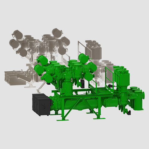
GE Vernova's Grid Solutions offers cutting-edge gas-insulated lines (GIL) up to 420 kV designed for both SF6 and SF6-free applications, leveraging more than 60 years of expertise in gas-insulated substation technology. This unique flexible design allows transmission system operators (TSOs) to purchase the SF6 version initially with the option to transition easily to the SF6-free g³ solution, ensuring compliance with emerging regulations on fluorinated greenhouse gases without compromising operational performance.
T155 DUAL GAS GIL
One 420 kV GIL design for SF₆ and SF₆-free
GE Vernova's Grid Solutions offers cutting-edge gas-insulated lines (GIL) up to 420 kV designed for both SF6 and SF6-free applications, leveraging more than 60 years of expertise in gas-insulated substation technology. This unique flexible design allows transmission system operators (TSOs) to purchase the SF6 version initially with the option to transition easily to the SF6-free g³ solution, ensuring compliance with emerging regulations on fluorinated greenhouse gases without compromising operational performance.
g³ gas GIL Specifications
| RATINGS | |||
| Voltage | kV | 362 | 420 |
| Standards | IEC/IEEE | IEC/IEEE | |
| Frequency | Hz | 50/60 | 50/60 |
| Withstand voltages, to earth - Short-duration power-frequency - Switching impulse - Lightning impulse | kV kV (peak) kV (peak) | 650 1050 1425 | 650 1050 1425 |
| Continuous current | A | 4,000/5,000 | 4,000/5,000 |
| Short-time withstand current | kA | 63 | 63 |
| Peak withstand current | kAp | 170 | 170 |
| Temperature | °C | -30 | -25/-30 |
Recommended Products & services
T155 DUAL GAS GIL
GE Vernova's Grid Solutions offers cutting-edge gas-insulated lines (GIL) up to 420 kV...
View MoreT210 up to 800 kV
Gas-Insulated Substations up to 800 kV
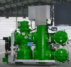
GE Vernova's T210 GIS is a field-proven solution with high availability that meets the challenges of networks up to 800 kV for power generation, transmission, distribution, tertiary and heavy industry applications. The T210 is one of the most compact GIS solutions available at 800 kV with a footprint 65% below the market average. It is comprised of small, light components making it easy to handle.
T210 up to 800 kV
Gas-Insulated Substations up to 800 kV
GE Vernova's T210 GIS is a field-proven solution with high availability that meets the challenges of networks up to 800 kV for power generation, transmission, distribution, tertiary and heavy industry applications. The T210 is one of the most compact GIS solutions available at 800 kV with a footprint 65% below the market average. It is comprised of small, light components making it easy to handle.
Customer Benefits

Main Characteristics
Environment friendliness
- Lowest gas weight on the market
- First-in-class SF₆ sealing system
High availability
- Design grounded by 50 years of experience
- Current transformers outside SF₆
Low costs of land and civil works
- Most compact GIS: footprint 65% below market average
Shortest site works
- Light and small components, easy to handle
Smart grid features
- full-digital monitoring, control and protection
Specifications
| General ratings | |
| Reference electrotechnical standards | IEEE/IEC |
| Voltages | 765/800 kV |
| Withstand voltages | |
| - Short-duration power-frequency, phase-to-earth / across isolating distance | 960/1270 kV |
| - Switching impulse, phase-to-earth / across open switching device | 1550/1200 (+653) kVp |
| - Lightning impulse, phase-to-earth / across isolating distance | 2100 /2100 (+460) kVp |
| Continuous current | 5000 A |
| Short-time withstand current | 50 kA |
| Peak withstand current | 125 kAp |
| Circuit-breaker ratings | |
| First-pole-to-clear factor | 1.3 |
| Short-circuit breaking current | 50 kA |
| Short-circuit making current | 125 kAp |
| Breaking time | <45ms |
| Pre-insertion resistor rating | >340 Ω |
| Mechanical endurance | M2 class |
| Disconnector ratings | |
| Bus-transfer current switching capability | 1600/40 (3200/300 option) A/V |
| Mechanical endurance | M2 class |
Recommended Products & services
T210 up to 800 <span class="text-lowercase">k</span>V
GE Vernova's T210 GIS is a field-proven solution with high availability that meets the...
View MoreT168 up to 550 kV
Gas-Insulated Substations up to 550 kV
GE Vernova makes the most of 50 years of experience in design, material selection, development, engineering, manufacturing and servicing of gas-insulated substations. GE Vernova's T168 GIS meet the challenges of networks up to 550 kV for all applications: power generation, transmission and heavy industry.
The T168 is compact and accessible, with a bay footprint 12% below previous version.
T168 up to 550 kV
Gas-Insulated Substations up to 550 kV
GE Vernova makes the most of 50 years of experience in design, material selection, development, engineering, manufacturing and servicing of gas-insulated substations. GE Vernova's T168 GIS meet the challenges of networks up to 550 kV for all applications: power generation, transmission and heavy industry.
The T168 is compact and accessible, with a bay footprint 12% below previous version.
Customer Benefits

Characteristics
Environment friendliness
- Gas mass reduced by 6% compared with previous version
- First-in-class SF₆ sealing system
- Advanced gas management systems
High availability
- Reliability is founded on GE Vernova’s extensive experience at 550 kV
- Current transformers outside SF₆
- Outstanding accessibility: drives and accessories at easy reach
Low costs of land and civil works
- Bay volume reduced by 12% compared to previous models
Smart grid features
- Full-digital monitoring, control and protection
Ratings
| Bay | ||
| Reference electrotechnical standards | IEC/GB | |
| Voltage | kV | 550 |
| Withstand voltages | ||
| Short-duration power-frequency, phase-to-earth/across open switching device | kV | 740 / 740 (+315) |
| Switching impulse, phase-to-earth / across isolating distance | kVp | 1 300 / 1 175 (+450) |
| Lightning impulse, phase-to-earth / across open switching device | kVp | 1 675 / 1 675 (+450) |
| Frequency | Hz | 50 / 60 |
| Continuous current | A | up to 6300 |
| Short-time withstand current | kA | 63 |
| Peak withstand current | kAp | 170 |
| Duration of short-circuit | s | 3 |
| Installation | indoor/outdoor | |
| CIRCUIT-BREAKER RATINGS | ||
| First-pole-to-clear factor | 1.3 | |
| Short-circuit breaking current | kA | 63 |
| Short-circuit making current | kAp | 170 |
| Operating sequence | O-0.3s-CO-3 min-CO/CO-15s-CO | |
| Capacitive switching | Class | C2 |
| DISCONNECTOR AND LOW-SPEED EARTHING SWITCH RATINGS | ||
| Capacitive current switching | A | 0.5 |
| Bus-transfer current switching capability | A / V | up to 4000 / 100 |
| MAKE-PROOF EARTHING SWITCH RATINGS | ||
| Making current capability | kAp | 170 |
| Switching capability-electromagnetic coupling | A / kV | up to 200 / 25 |
| Switching capability-electrostatic coupling | A / kV | up to 50 / 50 |
| other data available on request. | ||
Recommended Products & services
T168 up to 550 <span class="text-lowercase">k</span>V
GE Vernova makes the most of 50 years of experience in design, material selection,...
View MoreB105 up to 245 kV
Gas-Insulated Substations up to 245 kV
GE Vernova's B105 GIS is a compact, field-proven solution with high availability that meets the challenges of networks up to 245 kV for power generation, transmission, distribution, tertiary and heavy industry applications. The B105 is available in several ratings:
B105 up to 245 kV
Gas-Insulated Substations up to 245 kV
GE Vernova's B105 GIS is a compact, field-proven solution with high availability that meets the challenges of networks up to 245 kV for power generation, transmission, distribution, tertiary and heavy industry applications. The B105 is available in several ratings:
Customer Benefits
Main Characteristics
Environment friendliness
- Low gas weight
- Advanced SF₆ sealing system
- Smart grid features including full-digital monitoring, control and protection
High availability
- One of the best experiences and high data reliability
- Current transformers outside SF₆
- Pure-spring circuit breaker drives
- State-of-the-art maintenance isolating device: major repair and HV tests with no more than 1 bay down
- Drives and accessories at easy reach
Low costs of land and civil works
- One of the most compact GIS with single-phase enclosures only: bay footprint up to 50% below market average depending on kV rating
- Complete bays assembled, wired, tested and shipped
- Light and small single-phase components, easy to handle
Specifications
| General ratings | |
| Reference electrotechnical standards | IEC/IEEE/GB |
| Voltages | up to 245 kV |
| Withstand voltages | |
| - Short-duration power-frequency, phase-to-earth / across isolating distance | 460/530 kV |
| - Lightning impulse, phase-to-earth / across isolating distance | 1050/1200 kVp |
| Frequency | 50/60 Hz |
| Continuous current | 3150/4000 A |
| Short-time withstand current | 50/63 kA |
| Peak withstand current | 135/170 kAp |
| Duration of short-circuit | 3s |
| Installation | Indoor/outdoor |
| Ambient temperature range | down to -25 / up to +55 °C |
| Circuit-breaker ratings | |
| First-pole-to-clear factor | 1.3-1.5 |
| Short-circuit breaking current | 50/63 kA |
| Short-circuit making current | 135/170 kAp |
| Operating sequence | O-0.3s-CO-3 min-CO/CO-15s-CO |
| Drive type (three-phase or single-phase) | Pure-spring |
| Breaking time | <50 ms |
| Closing time | <100 ms |
| Mechanical endurance | M2 class |
| Capacitive switching | C2 class |
| Disconnector and low-speed earthing switch ratings | |
| Capacitive current switching | 0.25 A |
| Bus-transfer current switching capability | 1600 A / 20 V |
| Mechanical endurance | M2 class |
| Make-proof earthing switch ratings | |
| Making current capability | 135/170 kAp |
| Switching capability - electromagnetic coupling | 80 A / 2 kV |
| Switching capability - electrostatic coupling | 3 A / 12 kV |
| Mechanical endurance | M1 class |
Recommended Products & services
B105<span class="text-lowercase">g</span> up to 245 <span class="text-lowercase">k</span>V
The B105g SF₆-free GIS is part of GRiDEA, our portfolio of solutions designed to...
View More
B105 up to 245 <span class="text-lowercase">k</span>V
GE Vernova's B105 GIS is a compact, field-proven solution with high availability that...
View MoreF35-170 kV
Gas-Insulated Substations up to 170 kV
Our F35 GIS is a field-proven solution offering high availability and reliability for networks up to 170 kV. It is ideally suited for a wide range of applications, including power generation, transmission, distribution, commercial, and heavy industrial sectors. The F35-170 kV GIS uses SF₆ gas as both switching and insulating medium.
The F35-170 kV GIS will soon transition to a SF₆-free version, with the integration of our g³ gas technology planned in 2026. This evolution supports a more decarbonized grid while maintaining the same high level of performance and reliability.
F35-170 kV
Gas-Insulated Substations up to 170 kV
Our F35 GIS is a field-proven solution offering high availability and reliability for networks up to 170 kV. It is ideally suited for a wide range of applications, including power generation, transmission, distribution, commercial, and heavy industrial sectors. The F35-170 kV GIS uses SF₆ gas as both switching and insulating medium.
The F35-170 kV GIS will soon transition to a SF₆-free version, with the integration of our g³ gas technology planned in 2026. This evolution supports a more decarbonized grid while maintaining the same high level of performance and reliability.
Main Characteristics
Environment friendliness
- Low gas weight
- Advanced SF₆ sealing system
- Smart grid features including full-digital monitoring, control and protection
- Available in g³ up to 145 kV
High availability
- One of the best experiences and high data reliability
- Current transformers outside SF₆
- Drives and accessories at easy reach
- Pure-spring circuit breaker drives
Low costs of land and civil works
- One of the most compact GIS with bay footprint up to 45% below market average depending on kV rating
- Up to 2 bays (145 kV), up to 3 bays (72.5 kV), and complete bays (170 kV) assembled, wired, tested and shipped
- Isolating device for voltage transformer / surge arrester
Applicable for wind turbines at 72.5 kV
- Handle more power while reducing energy losses
- A compact HV substation fits in the wind turbine
- Withstands harsh environments
- Short installation time
Specifications
| General ratings | |||
| Reference electrotechnical standards | IEC/IEEE/GB | IEC/IEEE/GB | IEC/IEEE |
| Voltages | 72.5 kV | 145 kV | 170 kV |
| Withstand voltages | |||
| - Short-duration power-frequency, phase-to-earth / across isolating distance | 140/160 kV | 275/315 kV | 325/375 kV |
| - Lightning impulse, phase-to-earth / across isolating distance | 325/375 kVp | 650/750 kVp | 750/860 kVp |
| Frequency | 50/60 Hz | 50/60 Hz | 50/60 Hz |
| Continuous current | up to 2500A | up to 3150A | up to 4000A |
| Short-time withstand current | 31.5 kA | 40 kA | 50 kA |
| Peak withstand current | 85 kAp | 100/108 kAp | 125/130 kAp |
| Duration of short-circuit | 3s | 3s | 3s |
| Installation | Indoor | Indoor/outdoor | Indoor |
| Ambient temperature range | down to -30 / up to +55 °C | down to -30 / up to +55 °C | down to -25 / up to +55 °C |
| Circuit-breaker ratings | |||
| First-pole-to-clear factor | 1.5 | 1.5 | 1.5 |
| Short-circuit breaking current | 31.5 kA | 40 kA | 50 kA |
| Short-circuit making current | 80/82 kAp | 100/108 kAp | 125/130 kAp |
| Operating sequence | O-0.3s-CO-3 min-CO/CO-15s-CO | O-0.3s-CO-3 min-CO/CO-15s-CO | O-0.3s-CO-3 min-CO/CO-15s-CO |
| Drive type (three-phase or single-phase) | Pure-spring | Pure-spring | Pure-spring |
| Breaking time | 50 ms | 50 ms | 50 ms |
| Closing time | 70 ms | 95 ms | 100 ms |
| Mechanical endurance | M2 class | M2 class | M2 class |
| Capacitive switching | C2 class | C2 class | C2 class |
| Disconnector and low-speed earthing switch ratings | |||
| Capacitive current switching | 0.1 A | 0.1 A | 0.1 A |
| Bus-transfer current switching capability | 1600/10 A / V | 2520/20 A / V | 1600/10 A / V |
| Mechanical endurance | M2 class | M2 class | M2 class |
| Make-proof earthing switch ratings | |||
| Making current capability | 80/82 kAp | 100/108 kAp | 125/130 kAp |
| Switching capability - electromagnetic coupling | 80/2 A / kV | 80/2 A / kV | 80/2 A / kV |
| Switching capability - electrostatic coupling | 2/6 A / kV | 2/6 A / kV | 3/9 A / kV |
| Mechanical endurance | M1 class | M1 class | M1 class |
Recommended Products & services
F35 72.5 <span class="text-lowercase">k</span>V Dual Gas GIS
Our innovative F35 Dual Gas GIS, 50 or 60 Hz, has been designed to drive decarbonization...
View More
F35-170 <span class="text-lowercase">k</span>V
Our F35 GIS is a field-proven solution offering high availability and reliability for...
View More
F35-145 <span class="lower-case">k</span>V Dual Gas GIS
Our F35-145 kV Dual-Gas GIS —compatible with both SF₆ and g³ gases—is designed to...
View MoreF35-145 kV Dual Gas GIS
SF₆ and SF₆-free g³-Gas-Insulated Substations up to 145 kV
Our F35-145 kV Dual-Gas GIS —compatible with both SF₆ and g³ gases—is designed to meet the demands of electrical networks up to 145 kV. It is ideally suited for a wide range of applications, including offshore and onshore wind power generation, distribution networks, infrastructure projects, and industrial installations.
F35-145 kV Dual Gas GIS
SF₆ and SF₆-free g³-Gas-Insulated Substations up to 145 kV
Our F35-145 kV Dual-Gas GIS —compatible with both SF₆ and g³ gases—is designed to meet the demands of electrical networks up to 145 kV. It is ideally suited for a wide range of applications, including offshore and onshore wind power generation, distribution networks, infrastructure projects, and industrial installations.
Main Characteristics
Environment friendliness
- SF₆-free using GE Vernova’s g³ gas mixture instead of SF₆
- No pollution transfer in form of raw material increase
- GWP of the gas mass reduced by 99%
- Advanced sealing system
High availability
- Same principles, interfaces, operating mechanisms for both product in g³ and SF₆
- Easy access to drives and accessories
- Pure-spring circuit breaker drives
Low costs of land and civil works
- One of the most compact GIS with bay footprint up to 45% below market average depending on kV rating allows to have low civil work and compact switchgear buildings
- Up to 2 bays 145 kV assembled, wired, tested and shipped
- Isolating device for voltage transformer and surge arrester
Smart Grid ready
- Smart grid features including full-digital monitoring, control and protection
- One of the best experiences and high data reliability
- Digital substation ready with LPITs (Low Power Instrument Transformers)
Specifications
| General ratings | |
| Reference electrotechnical standards | IEC |
| Voltages | Up to 145 kV |
| Insulating and switching medium | g³ gas mixture |
| Withstand voltages | |
| Short-duration power-frequency, phase-to-earth / across isolating distance | 275/315 kV |
| Lightning impulse, phase-to-earth / across isolating distance | 650/750 kVp |
| Frequency | 50 Hz |
| Continuous current | up to 3150 A |
| Short-time withstand current | 40 kA |
| Peak withstand current | 108 kAp |
| Duration of short-circuit | 3s |
| Circuit-breaker ratings | |
| First-pole-to-clear factor | 1.5 |
| Short-circuit breaking current | 40 kA |
| Short-circuit making current | 108 kAp |
| Operating sequence | O-0.3s-CO-3 min-CO |
| Drive type (three-phase or single-phase) | Pure-spring |
| Breaking time | 50ms |
| Closing time | 95ms |
| Mechanical endurance | M2 class |
| Capacitive switching | C2 class |
| Disconnector and low-speed earthing switch ratings | |
| Capacitive current switching | 0.1 A |
| Bus-transfer current switching capability | 2520/20 A / V |
| Mechanical endurance | M2 class |
| Make-proof earthing switch ratings | |
| Making current capability | 108 kAp |
| Switching capability - electromagnetic coupling | 80/2 A / kV |
| Switching capability - electrostatic coupling | 2/6 A / kV |
| Mechanical endurance | M1 class |
Recommended Products & services
F35 72.5 <span class="text-lowercase">k</span>V Dual Gas GIS
Our innovative F35 Dual Gas GIS, 50 or 60 Hz, has been designed to drive decarbonization...
View More
F35-170 <span class="text-lowercase">k</span>V
Our F35 GIS is a field-proven solution offering high availability and reliability for...
View More
F35-145 <span class="lower-case">k</span>V Dual Gas GIS
Our F35-145 kV Dual-Gas GIS —compatible with both SF₆ and g³ gases—is designed to...
View MoreGPM-F Field Ground Protection Module
Complete generator system protection
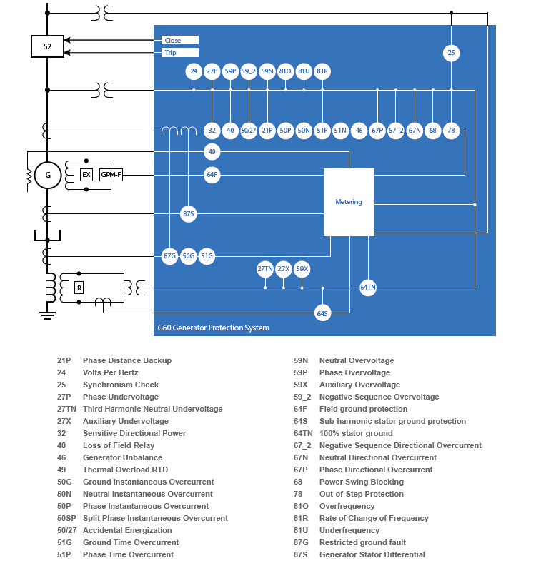
The field ground protection module, GPM-F works in combination with the Multilin G60 to detect ground faults in the field winding of the generator. Providing application flexibility, the field ground protection module can be configured for either single point injection or double point injection based on application requirements. The solution includes: two stage field ground detection, injected voltage and current supervision, brush lift-off detection, field over and under current elements and field ground fault location.
GPM-F Field Ground Protection Module
Complete generator system protection
The field ground protection module, GPM-F works in combination with the Multilin G60 to detect ground faults in the field winding of the generator. Providing application flexibility, the field ground protection module can be configured for either single point injection or double point injection based on application requirements. The solution includes: two stage field ground detection, injected voltage and current supervision, brush lift-off detection, field over and under current elements and field ground fault location.
Protection
- Two stage field ground resistance based element - 64F
- Wide range fault resistance coverage (1- 500Kohms)
- Injection frequency range 0.1 – 3Hz based on field winding capacitance
- Fault location feature while using single point injection
- Brush-lift off detection
- Injection blocking input for field flashing condition
- Supports redundant G60 configurations
- Field over current and field under current elements using dcmA input of G60
Diagnostics
- Power swing blocking and out-of-step tripping
- Backup distance
- Reverse / low forward power
- Restricted ground fault
- Overexcitation
- Generator unbalance
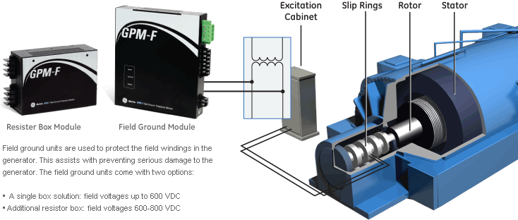
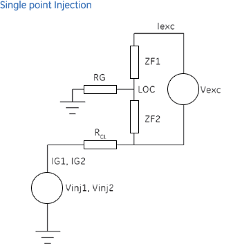
Providing application flexibility and diagnostic information, single point injection provides the ability to quickly identify the fault location in the field winding, thus reducing damaging the generator and reducing down-time. Single point injection has traditionally been the protection method used for generators with brushless excitation.
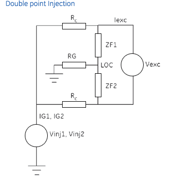
In addition to single point injection, the GPM-F module allows for ground fault detection via double point injection. Double point injection has typically been used on applications where generators are equipped with static excitation. When the GPM-F is connected for double point injection the fault location feature is not available. It is recommended that is fault location is required that the GPM-F be configured for single point injection.

GPM-S
Complete Generator System Protection
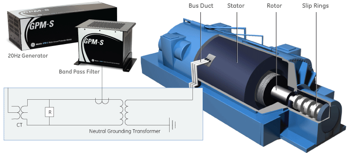
Stator ground module works in combination with GE Vernova’s Multilin G60 and MiCOM Agile P345 to provide a 100% stator ground fault protection that is operational during generator start-up, running and stopped conditions. In the 100% stator ground fault protection based on sub-harmonic injection, a 20Hz voltage is injected to detect ground faults at any point across 100% of the winding thereby protecting the complete stator winding and allowing early detection of stator ground fault conditions.
GPM-S
Complete Generator System Protection
Stator ground module works in combination with GE Vernova’s Multilin G60 and MiCOM Agile P345 to provide a 100% stator ground fault protection that is operational during generator start-up, running and stopped conditions. In the 100% stator ground fault protection based on sub-harmonic injection, a 20Hz voltage is injected to detect ground faults at any point across 100% of the winding thereby protecting the complete stator winding and allowing early detection of stator ground fault conditions.
Protection.
- Two stage stator ground resistance based element – 64S
- Wide range fault resistance coverage (1-20Kohms)
- Over current element for low resistance faults
- CT phase angle error compensation
Diagnostics
- Sub-harmonic voltage supervision
- Sub-harmonic current supervision
- Extensive internal diagnostics in the module with critical-fail relay
- The 100% stator ground fault protection is based on sub-harmonic injection
- 20Hz voltage is injected to detect ground faults at any point across 100% of the winding
- The stator ground module works in combination with the G60 or P345 to provide 100% stator ground fault protection
- Operational during generator start-up, running and stopped conditions
20 Hz Injection Module
Using sub-harmonic injection provides early detection of stator ground fault conditions. This is accomplished by the injection module generating a square wave pulse of 20Hz with a magnitude of +/-26V into the stator winding. The injection module monitors the frequency and magnitude of the signal it generates which allows for the Stator module to determine if a ground fault has occurred in the stator winding. In addition, the stator module is also equipped with a critical-fail relay that can be wired to alarm failure of the module.
Coupling Filter
The coupling filter is used to meet two functions: to smooth the square wave and convert it into a sine wave and to protect the injection module from AC voltage impressed from the secondary of neutral grounding transformer. Coupling filter contains only passive components. It also contains voltage divider circuits to be used on applications with NGT secondary voltage greater than 500V
Multilin 889
Comprehensive Protection and Management
The Multilin 889 relay, a member of the Multilin 8 Series protective relay platform, has been designed for the protection, control, monitoring and management generators and in-zone transformers used in both industrial and utilities applications.
The Multilin 889 provides advanced, high-speed protection, extensively customizable programmable logic, and flexible configuration capabilities, to maximize the operational performance and life of critical generators.
Full Color Graphical HMI Front Display
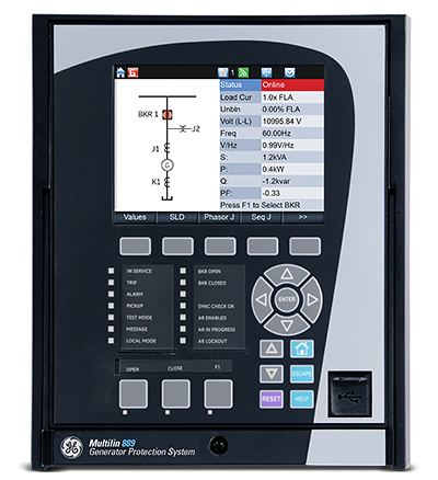
A large, full color Graphic Control Panel (GCP) ensures clear representation of critical status and measurements. The 8 Series offers two options for front panels:
- 10 Programmable Push buttons with 12 programmable LEDs
- 3 Programmable Push buttons and 12 programmable LEDs
Switchgear Control and Configurable SLD
The Multilin 8 Series provides a configurable dynamic SLD up to six (6) pages for comprehensive switchgear control of up to 3 breakers and 9 disconnect switches; including interlocks. Up to 15 digital and metering status elements can be configured per SLD page.
Platform Overview
The Multilin 8 Series platform delivers the highest level of quality, reliability and performance with…
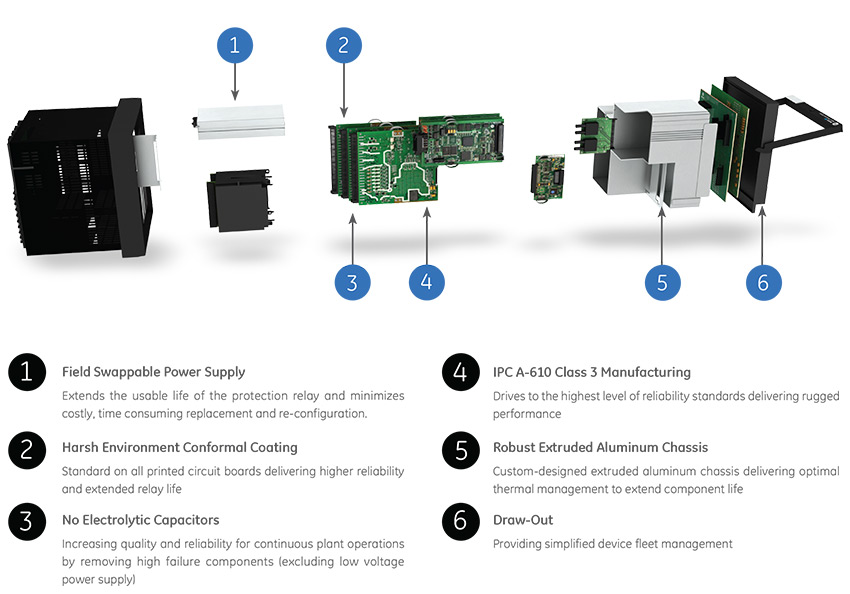
Innovative Technology & Design
- Patented environmental monitoring and diagnostics helps visibility on change in environmental parameters
- Advanced, flexible and embedded communications: IEC® 61850 Ed2, IEC 62439/PRP, Modbus® RTU & TCP/IP, DNP3.0, IEC 60870-5-104, IEC 60870-5-103
- Single setup and configuration across the platform
- Field swappable power supply
- Draw-out design simplifies testing, commissioning and maintenance, thereby increasing process uptime
- Optional Wi-Fi connectivity minimizes system configuration and provides safe relay programming and diagnostic retrieval
- Elimination of electrolytic capacitors
Exceptional Quality & Reliability
- IPC A-610-E Class 3 Manufacturing standards – highest industry standards for electronic manufacturing
- Highest reliability standards for electronics testing
- Environmental Stress Screening and full functional testing
- Rated for IP54 applications
- Standard Harsh Conformal Coating
Uncompromising Service & Support
- Covered under GE Vernova’s 10 year warranty plan
- Fully designed, tested and assembled at GE Vernova facilities
Multilin 889 Overview
The 889 has been designed for the protection, control, and management of generators and associated unit transformers in critical utility and industrial applications.
Applications:
- Comprehensive protection from small to large generators
- Industrial or utility power generation
- Co-generation and renewable generation applications
- Unit Transformer Protection applications
Multilin 889 feeder protection relay functional block diagram
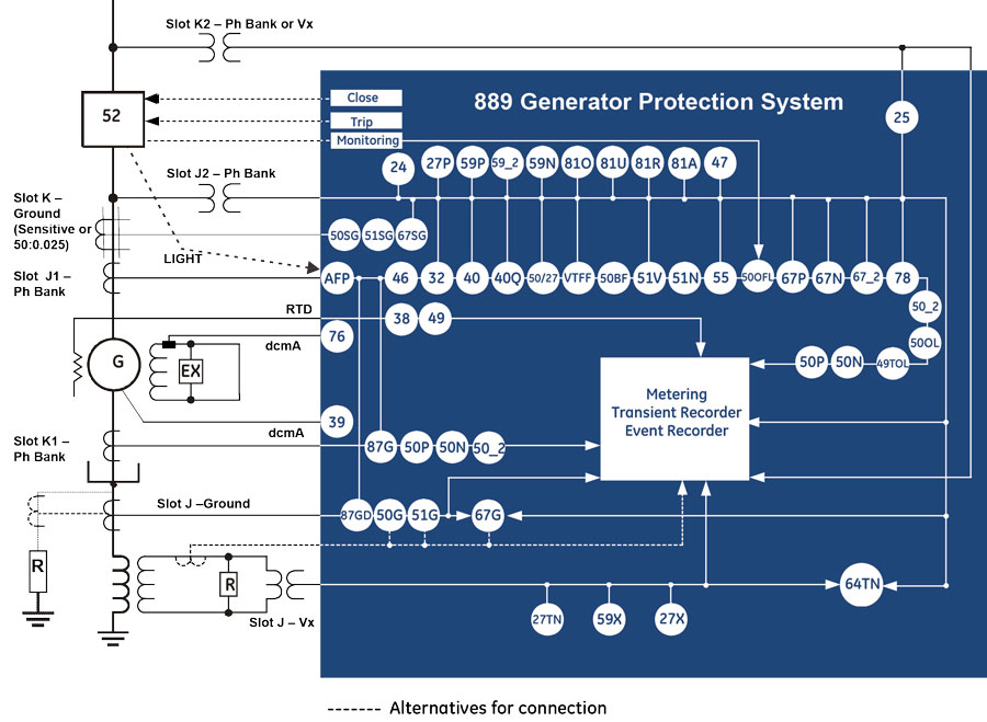
ANSI Device Numbers & Functions
| Device Number | Function |
|---|---|
| 24 | Volts per Hertz |
| 25 | Synchrocheck |
| 27P | Phase Undervoltage |
| 27X | Auxiliary Undervoltage |
| 27TN | Third Harmonic Neutral Undervoltage |
| 32 | Directional Power |
| 38 | Bearing Overtemperature (RTD) |
| 39 | Bearing Vibration (dcmA) |
| 40 | Loss of Excitation |
| 40Q | Reactive Power |
| 46 | Generator Unbalance |
| 47 | Phase Reversal |
| 49 | Thermal (RTD) |
| 49TOL | Thermal Overload |
| 50/27 | Inadvertent Energization |
| 50BF | Breaker Failure |
| 50G | Ground Instantaneous Overcurrent |
| 50SG | Sensitive Ground Instantaneous Overcurrent |
| Device Number | Function |
|---|---|
| 50N | Neutral Instantaneous Overcurrent |
| 50P | Phase Instantaneous Overcurrent |
| 50_2 | Negative Sequence Instantaneous Overcurrent |
| 50OFL | Offline Overcurrent |
| 50OL | Overload |
| 51G | Ground Time Overcurrent |
| 51N | Neutral Time Overcurrent |
| 51SG | Sensitive Ground Time Overcurrent |
| 51V | Voltage Restrained Time Overcurrent |
| 55 | Power Factor |
| 59N | Neutral Overvoltage |
| 59P | Phase Overvoltage |
| 59X | Auxiliary Overvoltage |
| 59_2 | Negative Sequence Overvoltage |
| 64TN | 100% Stator Ground using 3rd Harmonic Voltage Differential |
| 67G | Ground Directional Overcurrent |
| Device Number | Function |
|---|---|
| 67N | Neutral Directional Overcurrent |
| 67P | Phase Directional Overcurrent |
| 67SG | Sensitive Ground Directional Overcurrent |
| 67_2 | Negative Sequence Directional Element |
| 76 | Excitation Current Protection (dcmA) |
| 78 | Out-of-Step Protection |
| 81A | Frequency out-of-band |
| 81O | Overfrequency |
| 81U | Underfrequency |
| 81R | Frequency Rate of Change |
| 87G | Generator Stator Differential |
| 87O | Overall Unit (Gen-Xfrm) Protection |
| 87GD | Restricted Ground Fault |
| AFP | Arc Flash Protection |
| VTFF | VT Fuse Failure |
Generator Stator Differential Protection
The 889 utilizes high-speed dual slope differential protection for detecting and clearing of stator phase faults. Advanced CT saturation detection algorithms maintain immunity to saturation conditions that may be caused due to external disturbances through the use of a directional check that provides additional supervision and ensures the fault is internal to the generator before triggering it to trip.
Overall Generator & Transformer Differential Protection
The 889 can provide overall generator and transformer differential protection (87O). It covers the protection zones from the generator neutral to the GSU (Generator Step-Up) transformer’s High Voltage (HV) winding. This additional protection element provides backup to both Generator Stator Differential (87G) and a dedicated transformer differential in a transformer relay (i.e.: Multilin 845 Transformer Protection System). The 889 with this Generator-Transformer Differential protection supports transformer setup, provides enhanced protection security by including both restrained and unrestrained (instantaneous) differential protection.
100% Stator Ground
100% stator ground fault protection is provided through an overvoltage element and an adaptive voltage differential feature responding to the unbalance of the third harmonic at the machine terminals and at the neutral point. The 889 compares the machine neutral voltage and ground current to determine if ground directional faults are within or outside the generator.
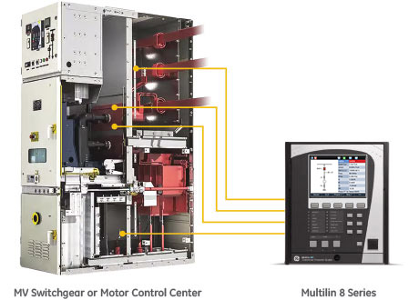
Integrated Arc Flash Protection
The Multilin 8 Series supports an integrated arc flash module providing constant monitoring of an arc flash condition within the switchgear, motor control control centers, or panelboards. With a 2ms protection pass, the 8 Series is able to detect light and overcurrent using 4 arc sensors connected to the 8 Series relay. In situations where an arc flash/fault does occur, the relay is able to quickly identify the fault and issue a trip command to the associated breaker thereby reducing the total incident energy and minimizing resulting equipment damage.
Self-monitoring and diagnostics of the sensors ensures the health of the sensors as well as the full length fiber cables. LEDs on the front panel display of the 889 can be configured to indicate the health of the sensors and its connections to the relay.
 Fast, reliable arc flash protection with light-based arc flash sensors integrated within the Multilin 8 Series of protection & control devices. With arc flash detection in as fast as 2msec, the costs associated with equipment damage and unplanned down
Monitoring & Diagnostics
The Multilin 889 includes high accuracy metering and recording for all AC signals. Voltage, current, and power metering are built into the relay as a standard feature. Current and voltage parameters are available as total RMS magnitude, and as fundamental frequency magnitude and angle.
Data Logging
The Multilin 889 includes high accuracy metering and recording for all AC signals. Voltage, current, and power metering are built into the relay as a standard feature. Current and voltage parameters are available as total RMS magnitude, and as fundamental frequency magnitude and angle.
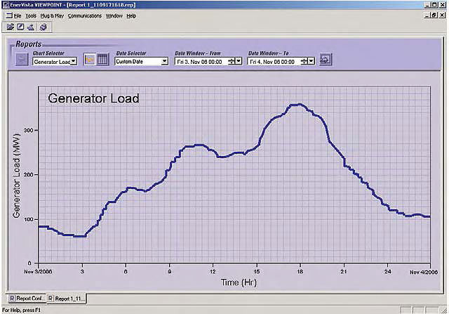
Log generator operating parameters to allow for analyzing generator loading and performance over weeks and months.
Dedicated Generator System Monitoring & Control
- Running Hours - The 889 can calculate/accumulate generator running hours, which may be of interest for periodic maintenance. if total running hours exceed the use-setting limit, the function would alarm the condition.
- Frequency OOB Accumulation - The Frequency Out-Of-Band (OOB) Accumulation feature provides diagnostic information and alarms based on the accumulated off-nominal (out-of-band) frequency operation time of a turbine over several frequency bands. This alarm can be used to schedule maintenance or other actions as desired
Advanced Generator Monitoring Diagnosis
The 889 can calculate/accumulate generator running hours, which may be of interest for periodic maintenance. if total running hours exceed the use-setting limit, the function would alarm the condition.
- Bearing vibration (Analog Input)
- Excitation current (Analog Input)
- Any generator transducer (dcmA) input monitoring
- Breaker Health
- Data logger, Oscillography, Event Recorder.
The Multilin 889 offers a comprehensive generator health report that provides an easy-to-read snapshot of a generator's health and operating condition. Based on graphical representation and trend values of the generator historical data, the 889 enables operators and asset managers to identify process issues and maintenance requirements before damage occurs and costly repairs are required.
Trip and Close Circuit Monitoring
The 889 relay provides Trip and Close Circuit Monitoring elements
Breaker Arcing Current
This element calculates an estimate of the per-phase wear on the breaker contacts by measuring and integrating the current squared passing through the breaker contacts as an arc. When the threshold is exceeded in any phase, the relay can set an output operand and set an alarm.
Breaker Health
The 889 relay provides breaker health information by monitoring and analyzing the operation count, arcing energy of breaking current, arcing time, tripping time, closing time and spring charging time if applicable
Environmental Monitoring
The 889 implements a patented environmental monitoring system that measures and provides operating condition information. Reliable and secure operation of the 889 relay and other electronic devices in the vicinity may be affected by environmental factors. The 869 relay has been designed to meet or exceed all required industry standards. Some operating conditions may be beyond those standards and reduce total lifespan of the device.

The 8 Series built-in environmental awareness feature (patent “Systems and methods for predicting maintenance of intelligent electronic devices”) collects the histograms of each operating condition from the point the device is put into service. Monitored environmental conditions include temperature, humidity and transient voltage. These parameters are now available as Flexelement to output alarms in case of limits reached due to Temperature, humidity or surges. (Please confirm if this is the part to replace the existing part).
The 889 implements a patented environmental monitoring system that measures and provides operating condition information. Reliable and secure operation of the 889 relay and other electronic devices in the vicinity may be affected by environmental factors. The 869 relay has been designed to meet or exceed all required industry standards. Some operating conditions may be beyond those standards and reduce total lifespan of the device.
Communications
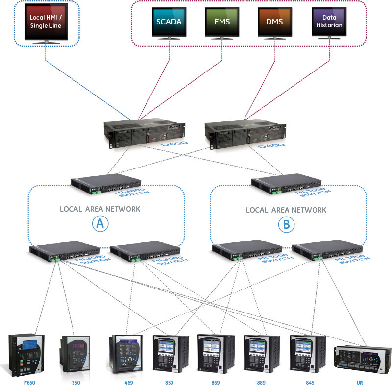
The 889 provides advanced communications technologies for remote data and engineering access, making it easy and flexible to use and integrate into new and existing infrastructures. Direct support for fiber optic Ethernet provides high-bandwidth communications, allowing for low-latency controls and high-speed file transfers of relay fault and event record information. The 889 also supports two independent IP addresses, providing high flexibility for the most challenging of communication networks.
Providing several Ethernet and serial port options, dual independent Ethernet Ports, and support for a wide range of industry standard protocols, the 889 enables easy, direct integration into DCS and SCADA systems. The 889 supports the following protocols:
- IEC 61850 Ed2, IEC 62439 / PRP
- DNP 3.0, IEC 60870-5-103, IEC 60870-5-104
- Modbus RTU, Modbus TCP/IP
The 889 has two interfaces as USB front port and Wi-Fi for ease of access to the relay. Wi-Fi Connectivity:
- Simplify set-up and configuration
- Simplify diagnostic retrieval
- Eliminate personnel in front of switchgear
- WPA-2 security

Cyber Security
The 869 cyber security enables the device to deliver full cyber security features that help operators to comply with NERC CIP guidelines and regulations.
AAA Server Support (Radius/LDAP)
Enables integration with centrally managed authentication and accounting of all user activities and uses modern industry best practices and standards that meet and exceed NERC CIP requirements for authentication and password management.
Role Based Access Control (RBAC)
Efficiently administrate users and roles within UR devices. The new and advanced access functions allow users to configure up to five roles for up to eight configurable users with independent passwords. The standard “Remote Authentication Dial In User Service” (Radius) is used for authentication.
Event Recorder (Syslog for SEM)
Capture all cyber security related events within a SOE element (login, logout, invalid password attempts, remote/local access, user in session, settings change, FW update, etc), and then serve and classify data by security level using standard Syslog data format. This will enable integration with established SEM (Security Event Management) systems.
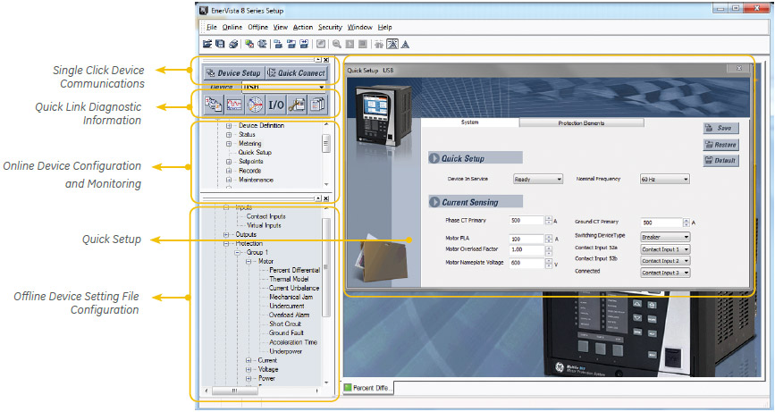
Software & Configuration
The EnerVista™ suite is an industry-leading set of software programs that simplifies every aspect of using the Multilin 869.
EnerVista provides all the tools to monitor the status of the protected asset, maintain the device and integrate the information measured by the Multilin 8 Series, into SCADA or DCS process control systems. The ability to easily view sequence of events is an integral part of the setup software, as postmortem event analysis is critical to proper system management.
EnerVista Launchpad
The setup tools within Launchpad allow for the configuration of devices in real-time, by communicating via serial, Ethernet or modem connections, or offline by creating device setting files to be sent to devices at a later time.
8 Series Setup Software
8 Series Setup Software is single setup and configuration tool across the platform and can reduce device setup and configuration time.
Simplified Setup & On-Going Maintenance
 Explore the 8 Series Retrofit Kit
8 Series Retrofit Kit
Retrofit Existing SR 489 Devices to the Multilin 889 in Minutes
Traditionally, retrofitting an existing relay has been a challenging, time consuming task often requiring re-engineering, new drawings, panel modifications, re-wiring and re-testing.
The 8 Series Retrofit Kit provides a quick, 3-step solution to upgrade previously installed SR 489 relays. With the new 8 Series Retrofit Kit users are able to install the 889 Generator Management System without modifying existing cutouts and wiring, and without any drawing changes or re-engineering time.
EnerVista 8 Series Setup Software provides automated setting file conversion. Once completed, a graphical report is provided to verify and call out any specific settings that may need attention.
Simply remove the upper, lower and low voltage terminal blocks and then remove the SR chassis from the panel. No need to disconnect any of the field wiring.
Insert the new 8 Series Retrofit chassis into the switchgear and simply plug-in the old terminal blocks - there is no need to make any cut-out modifications or push and pull cables.
Recommended Products & services

Multilin 889
The Multilin 889 relay, a member of the Multilin 8 Series protective relay platform, has...
View More