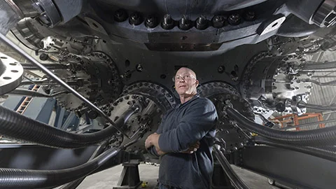



Overview

Protecting performance, reliability, and service life

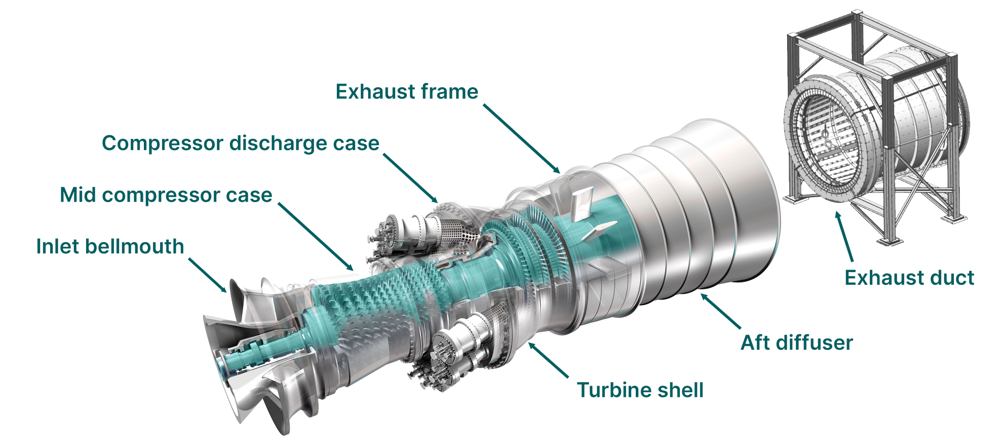
Gas turbine casings play a critical role in unit performance, reliability, and long-term operability. As essential structural components, they support alignment, define the gas path, transfer loads, provide containment, and enable access for maintenance. Over time, changes in casing condition can affect clearances, efficiency, outage scope, and overall machine reliability. With the right inspection and maintenance strategy, operators can identify issues earlier, plan repairs more effectively, and help extend service life.

Why casings matter

Casings do more than enclose the machine. They help define and maintain the internal geometry required for proper clearances, efficient air flow, and reliable operation. As units age, casing condition can be influenced by operating profile, fired hours, starts, temperature exposure, and maintenance quality.

For peaking units, frequent starts and stops can increase thermal fatigue. For base-loaded units, long-term high-temperature exposure can lead to creep-related deformation. In either scenario, the right response depends on engineering assessment — not age alone.

7f-exhaust-duct.png

Common casing challenges

Over time, gas turbine casings can experience wear, distortion, cracking, slippage, and other forms of structural degradation. Common issues may include:

  • Misalignment affecting rotor-to-casing clearances
  • Horizontal or vertical joint movement
  • Crack formation in high-stress areas
  • Deformation or out-of-roundness
  • Gouges, galling, and hardware-related damage
  • Leaks at joints or sealing surfaces
  • Corroded plugs or loosened retention hardware
  • Exhaust frame and diffuser wear, including flex seal issues

When left unaddressed, these conditions can contribute to blade rubs, performance losses, difficult disassembly and reassembly, increased outage scope, and in some cases forced outages or safety concerns.

Inspection and maintenance

Although casings are designed for long life, routine inspections remain important—especially during planned outages. Key inspection areas include:

  • Horizontal joint integrity
  • Vertical joint alignment and flange slippage
  • Four-way joint sealing
  • Casting transition areas
  • Out-of-roundness and distortion
  • Seals, plugs, gaskets, and anti-rotation features
  • Body-bound bolts, dowels, jacking bolts, and lifting lugs
  • Signs of corrosion, leaks, gouges, or discoloration

Addressing findings early can help prevent larger structural issues and support longer casing life with fewer unplanned interventions.

Needs assessment

Choosing the right casing strategy

Not every casing issue requires replacement. Depending on the severity and location of the damage, customers may be able to repair the casing, or may need to plan for replacement strategically. Decisions should be based on actual condition, operating history, and engineering evaluation. Contact us or reach out to your account manager to discuss the right casing strategy for your unit.

7f-casing-repair-1.png
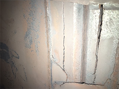
Repairable cracked exhaust diffuser

Repair

  • Best suited for localized damage where the casing remains serviceable
  • Addresses cracking, flange damage, gouges, and stud hole problems
  • Proactively extends asset life through periodic inspections, alignment checks, and timely maintenance
  • Restores integrity to prevent further deterioration and support continued operation
7f-casing-replace-1.png
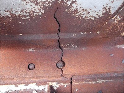
Non-repairable cracked turbine shell

Replace

  • Required when damage is too severe for practical or safe repair
  • Triggered by major deformation or through-wall cracking
  • Necessary when critical clearances can no longer be maintained
  • Requires early planning to manage longer lead times and complex outage scopes

Alignment is critical

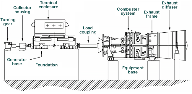
Once assembly is complete, the focus shifts to alignment. Casing alignment is essential to maintaining proper clearances and protecting both engine performance and long-term reliability. Over time, factors like casing slip in cyclic units or material creep in baseload units can alter the relationship between rotating and stationary components, increasing the risk of rubs and efficiency losses.

7f-casing-diagram.png


Key focus areas for alignment planning:

  • Schedule alignment checks at recommended intervals or during rotor replacements
  • Establish a clear baseline by tracking casing movement by flange
  • Integrate bearing alignment and dowel installation into your outage scope
  • Verify alignment diagrams and measurement points well in advance
  • Confirm early availability of all required shims and critical hardware

Review relevant GEK documents in the customer portal for more information on alignments.

Contact us

Let's talk about your 7F casings